Modular flowmeter

A flow meter, modular technology, applied in the direction of volume/mass flow generated by mechanical effects, through detection of dynamic effects of fluid flow, etc., can solve the problems of short service life, low precision, etc., to reduce wear, prolong service life, good aesthetic effect

Inactive Publication Date: 2016-11-02
山西传控电子科技有限公司
View PDF9 Cites 2 Cited by
  • Summary
  • Abstract
  • Description
  • Claims
  • Application Information

AI Technical Summary

Problems solved by technology

[0006] In order to solve the technical problems of low precision and short service life of the existing flow sensors, this solution provides

Method used


Image

  • Modular flowmeter
  • Modular flowmeter
  • Modular flowmeter

Examples


Example Embodiment

[0033] Example 1:

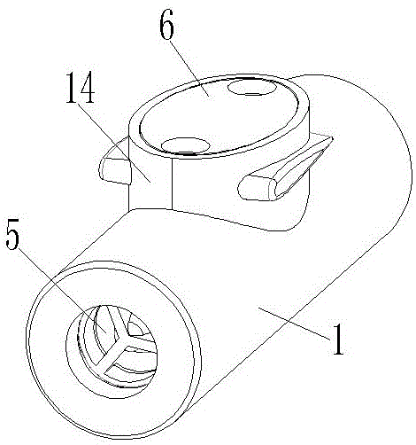
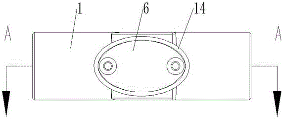
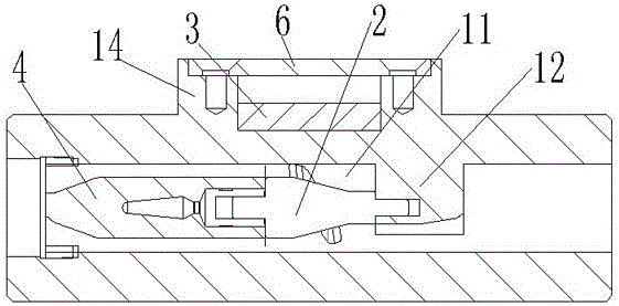
[0034] like figure 1 , figure 2 , image 3 and Figure 4 As shown, the modular flowmeter includes a casing 1 with a fluid channel 11 inside, a centripetal turbine 2 is installed in the fluid channel 11, and the materials of the casing 1 and the centripetal turbine 2 are nylon magnets. The center of the centripetal turbine 2 is a truncated cone-shaped turbine shaft 21, and a spiral blade 22 is installed on the side wall of the middle of the turbine shaft 21, which improves the conversion rate of the fluid and the rotational speed of the impeller. A sensor 3 is also mounted on the outer side of the housing 1 . When in use, install the flowmeter on the fluid pipeline to be measured according to the installation instructions. After the fluid to be measured passes through the fluid channel 11, the helical blade 22 of the centrifugal turbine 2 rotates under the impact of the fluid to be measured, and the sensor 3 detects the direction The rotational speed o...

Example Embodiment

[0035] Embodiment 2

[0036] like Figure 10 , Figure 11 and Figure 12 As shown, the difference between this embodiment and Embodiment 1 lies in the number of helical blades 22. In this embodiment, the number of helical blades 22 is two, and the rotation directions of the two helical blades 22 are the same. A spiral channel 23 is formed between them. After the fluid to be measured passes through the spiral channel 23, the fluid to be measured will generate a force opposite to the flow direction on the turbine, balancing part of the impact force of the fluid.

Example Embodiment

[0037] Embodiment 3

[0038] like image 3 , Image 6 , Figure 7 and Figure 9 As shown, the difference between this embodiment and the second embodiment is the installation method of the centripetal turbine 2. In this embodiment, a support 12 is fixed in the fluid channel 11, and a plurality of fan-shaped passages for fluid to pass through are opened on the support 12. Opening 5, a plug 4 is movably installed in the fluid channel 11. The material of the plug 4 is nylon. The installation methods of the plug 4 are diversified, and the snap connection, threaded connection and elastic connection can be selected. The turbine 2 is fixed on the support 12 to ensure that the centripetal turbine 2 will not sway randomly in the fluid channel 11, so as to avoid the unstable movement of the centripetal turbine 2 affecting the stability of flow monitoring.


PUM

PropertyMeasurementUnit
Helix angleaaaaaaaaaa
Taperaaaaaaaaaa

Abstract

The invention relates to a modular flowmeter, namely a modular flow sensor, and belongs to the technical field of real-time fluid flow monitoring. The modular flowmeter comprises a casing which is internally provided with a fluid passage, the fluid passage is internally provided with a centripetal turbine, the middle portion of the centripetal turbine includes a frustum-shaped turbine shaft, the sidewall of the middle portion of the turbine shaft is provided with two spiral blades, fluid flows from the end of a large sectional area of the turbine shaft to the end of a smaller sectional area of the turbine shaft, the circulation area of the fluid to be measured in the centripetal turbine increases gradually, the flow velocity reduces gradually, the pressure increases gradually, and thus, a thrust opposite to the flowing direction is generated for the turbine, part of an impact force acted on the centripetal turbine by the fluid to be measured is balanced, the frictional force of a bearing mounted behind the centripetal turbine is reduced, and the pressure loss of the centripetal turbine when measuring the fluid is low. The appearance of a submarine looks beautiful, and the modular flowmeter can be widely popularized and applied in the fluid monitoring field and the like.

Description

technical field [0001] The invention belongs to the technical field of real-time monitoring of fluid flow, and in particular relates to a modular flow sensor. Background technique [0002] The flow sensitivity of existing flow sensors of the same type is not high, especially the liquid flow meters of 5L / min--30L / min, mainly foreign manufacturers represented by Zimmer FT-110 series turbine flow sensors and small domestic manufacturers in Jiangsu and Zhejiang Provided that the price of the former is high, which is not conducive to promotion, while the price of the latter is extremely low, but its accuracy is low and it is easy to damage. The effective average lifespan is 1 month to 1 year. [0003] At the same time, for the impeller parameters of the small flow turbine flow sensor, the shape of the existing impeller in the industry is relatively simple, basically a cylindrical shaft or a metal rod shaft, and several types of blades are common. Cooperating with the blade, alth...

Claims


Application Information

Patent Timeline
IPC IPC(8): G01F1/28
CPCG01F1/28
Inventor 周勇杨利
Owner 山西传控电子科技有限公司
Why Eureka
Try Eureka