Lag screw

A screw and tension technology, applied in the field of medical devices, can solve the problems of easily piercing the femoral head, and achieve the effect of firm and reliable fixation, stability and effectiveness, and simple structure

Inactive Publication Date: 2016-11-09
TRAUSON CHINA MEDICAL INSTR COMPANY
View PDF3 Cites 0 Cited by
  • Summary
  • Abstract
  • Description
  • Claims
  • Application Information

AI Technical Summary

Problems solved by technology

[0003] The technical problem to be solved by the present invention is: in order to overcome the deficiency that the lag screw moves forward and easily penetrates the femoral head in the prior art, the present invention provides a lag screw, which has the advantages of simple structure and firm and reliable fixation of the lag screw

Method used


Image

  • Lag screw
  • Lag screw
  • Lag screw

Examples


Embodiment Construction

[0024] The present invention will be described in detail in conjunction with accompanying drawing now. This figure is a simplified schematic diagram only illustrating the basic structure of the present invention in a schematic manner, so it only shows the components relevant to the present invention.

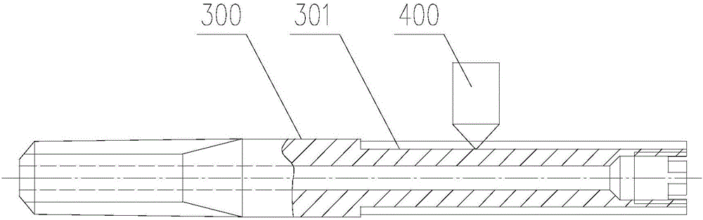
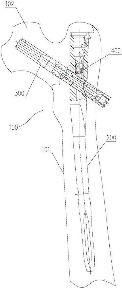
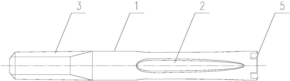
[0025] Such as figure 2 As shown, a lag screw assembly structure of the present invention includes a femur 100, an intramedullary nail 200, a lag screw 300 and a fastening screw 400, the intramedullary nail 200 penetrates the femoral body 101 of the femur 100 from top to bottom, and the lag screw 300 penetrates the intramedullary nail 200 along the direction of the femoral head 102, the fastening screw 400 is placed in the inner hole of the intramedullary nail 200, and is threadedly connected with the intramedullary nail 200, and the spherical head of the fastening screw 400 is embedded in the lag screw 300 The anti-rotation groove 2 is in contact with the anti-rotation groove...


PUM


Abstract

The invention provides a lag screw which comprises a screw body. The outer wall of the screw body is provided with an anti-rotation groove extending in the axial direction. The anti-rotation groove comprises an abutting portion. The bottom face of the abutting portion is gradually upwarped from front to rear in the axial direction. According to the lag screw, the abutting portion with the certain inclination angle is adopted in the anti-rotation groove for limiting the forward motion of the lag screw, the lag screw is prevented from puncturing thighbone, a limiting portion with a certain angle is adopted for limiting reverse disengagement of the lag screw, and meanwhile the anti-rotation groove can also limit axial rotation of the lag screw. The lag screw has the advantages of being simple in structure, and firm and reliable in fixing, and treatment stability and effectiveness are ensured.

Description

technical field [0001] The invention relates to the technical field of medical instruments, in particular to a lag screw. Background technique [0002] In the surgery for treating fractures, intramedullary nails are usually used to fix the fracture site. The intramedullary nails need lag screws to fix them on the bones of the human body, such as figure 1 As shown, in order to prevent the lag screw 300 from rotating axially, an L-shaped anti-rotation groove 301 is provided on the outer wall of the lag screw 300, and the fastening screw 400 abuts in the L-shaped anti-rotation groove 301, which can prevent the lag screw 300 from Axial rotation, at the same time, when the human body is active, the movement tendency of the femur is to break free from the suspension of the lag screw 300, that is, the lag screw 300 has a tendency to withdraw from the femur, because the front end of the L-shaped anti-rotation groove 301 and the fastening screw The blocking of 400 can prevent the la...

Claims


Application Information

Patent Timeline
Patent Type & Authority Applications(China)
IPC IPC(8): A61B17/72
CPCA61B17/725A61B17/7258
Inventor 裴磊于圣泰
Owner TRAUSON CHINA MEDICAL INSTR COMPANY
Why Eureka
Try Eureka