Multi-pipe type centrifugal solid-liquid separation machine

A solid-liquid separator and multi-tube technology, which is applied in centrifuges and other directions, can solve the problems of difficult control of revolution speed and rotation speed, short life of rotation drive belt, and difficult maintenance of filter cartridge bearings, etc., so as to achieve easy control of rotation speed, The effect of large driving torque and easy maintenance and operation

Active Publication Date: 2016-11-09
CHINA UNIV OF PETROLEUM (EAST CHINA)
View PDF7 Cites 8 Cited by
  • Summary
  • Abstract
  • Description
  • Claims
  • Application Information

AI Technical Summary

Problems solved by technology

However, according to the patent ZL201310098406.3, there are still deficiencies in the driving mode of the forced discharge self-cleaning centrifugal dryer, the disassembly method of the filter cartridge, and the structure of the static feed port, dynamic feed port, top bearing, filter cartridge bearing and other components. ; and there is no control box, it is difficult to control t

Method used


Image

  • Multi-pipe type centrifugal solid-liquid separation machine
  • Multi-pipe type centrifugal solid-liquid separation machine
  • Multi-pipe type centrifugal solid-liquid separation machine

Examples


Example Embodiment

[0037] Below with reference to accompanying drawing, be further described:

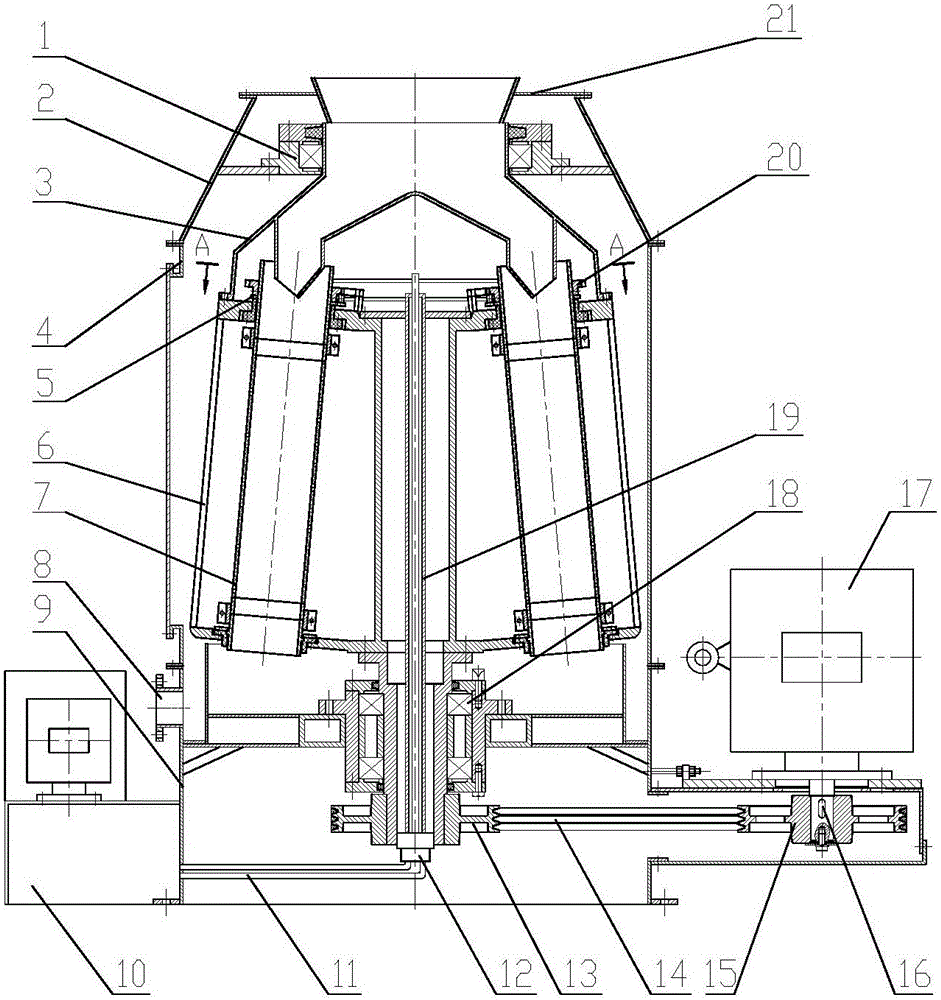
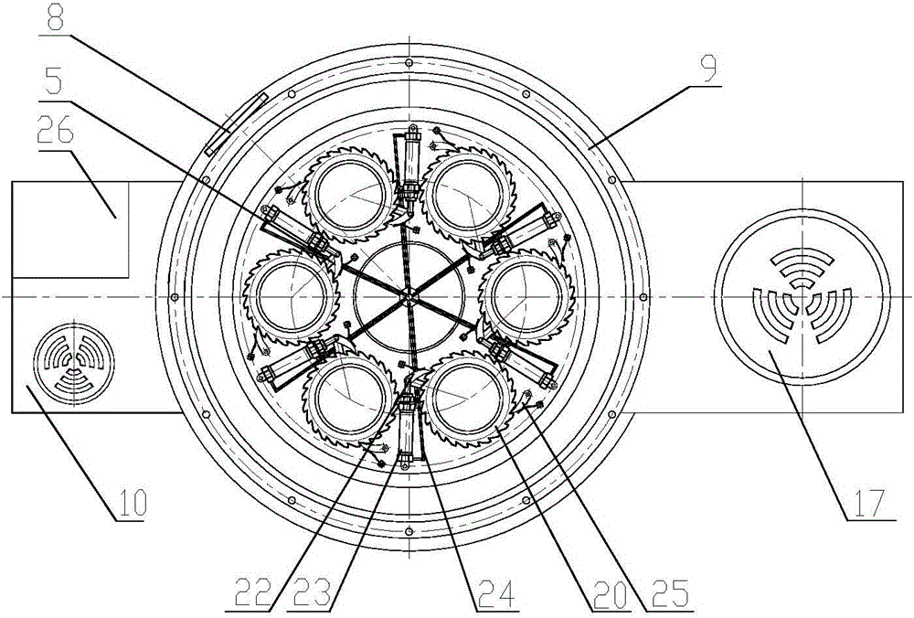
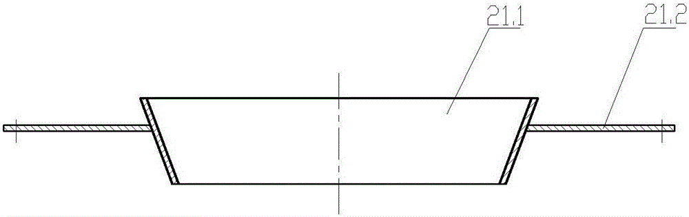
[0038] According to the present invention, as Figure 1 to Figure 2 1 is the top bearing assembly, 2 is the upper cone shell, 3 is the moving feed port, 4 is the main housing, 5 is the drive handle, 6 is the drum assembly, 7 is the filter cartridge, and 8 is the liquid outlet , 9 is skirt, 10 is hydraulic station, 11 is main oil pipe, 12 is dynamic and static joint, 13 is slave pulley, 14 is belt, 15 is main pulley, 16 is key, 17 is main motor, 18 is transmission component , 19 is the main oil pipe assembly, 20 is the ratchet, 21 is the static feed port, 22 is the driving pawl, 23 is the hydraulic cylinder, 24 is the oil distribution pipe, 25 is the stop pawl, and 26 is the control box.

[0039] like Figure 1 to Figure 2 The multi-tube centrifugal solid-liquid separator shown is connected to the static feed port 21, the upper conical shell 2, the main shell 4 and the skirt seat 9 in sequence from t...


PUM


Abstract

The invention discloses a multi-pipe type centrifugal solid-liquid separation machine. The multi-pipe type centrifugal solid-liquid separation machine is characterized by comprising a stationary feed inlet, an upper conical shell, a main shell, a skirt base, a movable feed inlet, a revolving drum assembly, a transmission assembly, a top bearing assembly, filter cartridges, a liquid outlet, a main motor, a key, a main belt wheel, a belt and a slave belt wheel, and further comprising ratchet wheels, driving pawls, stop pawls, driving handles, hydraulic cylinders, branch oil pipes, a main oil pipe assembly, a movable-stationary connector, a main oil pipe, a hydraulic station and a control cabinet; the exterior is sequentially connected with the stationary feed inlet, the upper conical shell, the main shell and the skirt base from top to bottom, and the movable feed inlet, the revolving drum assembly and the transmission assembly are sequentially and coaxially assembled inside; the six to eight filter cartridges are evenly installed in the circumferential direction of the revolving drum assembly, the angle between the axes of the filter cartridges and the central axis of the revolving drum assembly is three to seven degrees, and a ratchet wheel mechanism and a hydraulic system are matched to drive the filter cartridges to rotate; and the control cabinet is connected with the main motor and the hydraulic station through cables. The problems that meshes of filter screens are prone to blockage and filter production is not continuous are solved, and the multi-pipe type centrifugal solid-liquid separation machine is simple in structure and convenient to maintain.

Description

Technical field: [0001] The invention relates to a multi-tube centrifugal solid-liquid separator, in particular to a multi-tube centrifugal solid-liquid separator with self-cleaning function and continuous filtration production. Background technique: [0002] Filtration technology is widely used in petroleum, chemical industry, mining, medicine, food and other fields. Its main characteristics are: the material flows to the filter medium, the liquid passes through the filter medium, and the larger solid particles are blocked on the side of the filter medium to form a filter cake. The filter pores of the media may be blocked and the filter resistance increases. When the filter cake accumulates to a certain thickness, the filter holes are completely blocked, and the filter resistance increases significantly, so the filter medium needs to be cleaned, and the filter production is often carried out intermittently. [0003] I have previously applied for a patent "A Forced Unloadin...

Claims


Application Information

Patent Timeline
IPC IPC(8): B04B5/02B04B9/08B04B9/10B04B11/04B04B7/08B04B7/16
CPCB04B5/02B04B7/08B04B7/16B04B9/08B04B9/10B04B11/04B04B2011/046
Inventor 王宗明逄发周英宝段希利
Owner CHINA UNIV OF PETROLEUM (EAST CHINA)
Why Eureka
Try Eureka