
Optical fiber ferrule assembling equipment

A technology for optical fiber ferrule and assembly equipment, applied in assembly machines, metal processing equipment, optics, etc., can solve problems such as no advantage, fiber damage, shortening fiber service life, etc., to achieve a high degree of automation, reduce production costs, and reduce labor. cost effect

Pending Publication Date: 2016-11-09
SHAOXING AOCHUANG INTELLIGENT TECH CO LTD
View PDF7 Cites 27 Cited by
  • Summary
  • Abstract
  • Description
  • Claims
  • Application Information

AI Technical Summary

Problems solved by technology

The demand for optical fiber heads is huge, and manual assembly of optical fiber ferrules requires a large number of operators to engage in tedious and inefficient work, and the labor cost of my country has no advantage compared with Southeast Asian countries.
[0003] The fiber core is very small and fragile, and it is prone to fiber breakage and damage during manual fiber stripping. In addition, manual fiber stripping will cause a large number of undetectable micro-damages to the fiber core, reducing the service life of the fiber
[0004] The optical fiber should not be subjected to excessive force during the operation in the non-stripped area. Manual operation is not easy to control the force, which will cause more damage to the optical fiber.

Method used


Image

  • Optical fiber ferrule assembling equipment
  • Optical fiber ferrule assembling equipment
  • Optical fiber ferrule assembling equipment

Examples


Embodiment Construction

[0031] In order to make the technical means, creative features, objectives and effects of the present invention easy to understand, the present invention will be further explained below in conjunction with specific embodiments.

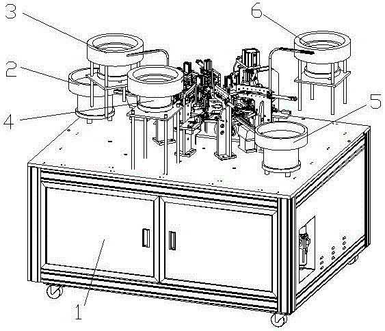
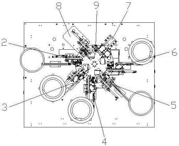
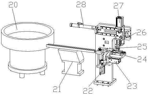
[0032] Such as Figure 1 to Figure 13 As shown, it shows a fiber optic ferrule assembly equipment to assemble the fiber optic ferrule, including a base 1, a turntable 9 assembled on the base 1, and an inner shell reclaiming mechanism 2 arranged on the base 1. , The ferrule reclaiming mechanism 3 assembled on the base 1, the spring feeding mechanism 4 assembled on the base 1, the spring limit card mechanism 5 assembled on the base 1, the assembly on the base 1 The tail handle feeding mechanism 6, the tail handle punching mechanism 7 arranged on the base 1, and the unloading mechanism 8 arranged on the base 1, the turntable 9 rotates counterclockwise, the inner shell reclaiming mechanism 2, The ferrule reclaiming mechanism 3, the spring feeding mechanism ...


PUM


Abstract

The invention relates to optical fiber ferrule assembly equipment for assembling optical fiber ferrules. The optical fiber ferrule assembly equipment comprises a base as well as a rotary table, an inner casing taking mechanism, a ferrule taking mechanism, a spring feeding mechanism, a spring limiting and clamping mechanism, a tail handle feeding mechanism, a tail handle stamping mechanism and a discharging mechanism which are arranged on the base, wherein the rotary table rotates counterclockwise; the inner casing taking mechanism, the ferrule taking mechanism, the spring feeding mechanism, the spring limiting and clamping mechanism, the tail handle feeding mechanism, the tail handle stamping mechanism and the discharging mechanism are all connected with the rotary table and are distributed along the rotary table in a counterclockwise direction sequentially; the optical fiber ferrules are assembled along with the rotation of the rotary table from the inner casing taking mechanism to the discharging mechanism; the optical fiber ferrule assembly equipment is high in automation degree and can improve the production efficiency.

Description

Technical field [0001] The invention relates to the field of optical fiber ferrule manufacturing, in particular to an optical fiber ferrule assembly equipment. Background technique [0002] With the rapid development of the modern communication industry, optical fiber communication technology has gradually replaced cable transmission technology, and the demand for optical fiber ferrules is very large. At present, most of the domestic fiber optic head production is still at the manual stage. The demand for optical fiber heads is huge, and manual assembly of optical fiber ferrules requires a large number of operators to engage in tedious and inefficient work, and labor costs in my country have no advantage compared with Southeast Asian countries. [0003] The fiber core is very small and fragile, and it is prone to fiber breakage and damage during manual fiber stripping. In addition, manual fiber stripping will cause a large amount of undetectable small damage to the fiber core, red...

Claims


Application Information

Patent Timeline
Patent Type & Authority Applications(China)
IPC IPC(8): B23P21/00B23P19/00G02B6/38
CPCG02B6/3898B23P19/004B23P19/006B23P21/00
Inventor 徐金宝吕忠光卜国飞
Owner SHAOXING AOCHUANG INTELLIGENT TECH CO LTD
Learn More