
Performed composite propeller blade of ship and manufacturing method of performed composite propeller blade

A composite material and preform technology, which is used in the construction of rotating propellers, ships, ships, etc., can solve the problems of difficult three-dimensional braiding preforms, difficult to ensure vibration noise, complex shapes, etc., to avoid delamination and peeling, Excellent acoustic characteristics and improved stealth performance

Active Publication Date: 2016-11-09
中国船舶重工集团公司第七〇二研究所
View PDF4 Cites 12 Cited by
  • Summary
  • Abstract
  • Description
  • Claims
  • Application Information

AI Technical Summary

Problems solved by technology

The RTM injection molding process often uses fiber cloth layering or weaving methods to make preforms. If the layering method is used, the problem of delamination at the guide and edge will also occur, and the layer will move slightly due to the injection molding process. , it is also difficult to ensure that the internal structure of all blades prepared by the same mold is exactly the same, which will cause vibration and noise problems; in addition, for marine propellers, which have complex shapes and high precision requirements, three-dimensional braided preforms are more difficult and costly. high

Method used


Image

  • Performed composite propeller blade of ship and manufacturing method of performed composite propeller blade
  • Performed composite propeller blade of ship and manufacturing method of performed composite propeller blade

Examples


Embodiment 1

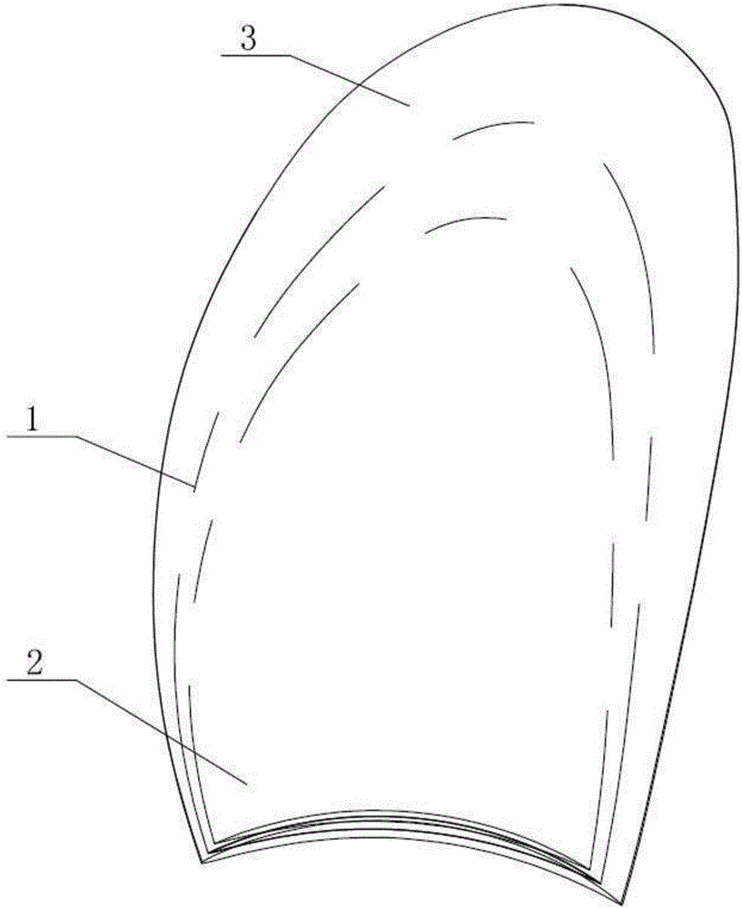
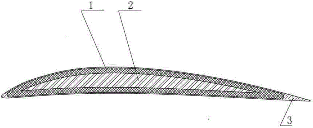
[0027] Such as figure 1 , figure 2 Shown, a kind of ship composite material propeller blade preform preparation method comprises the following steps:

[0028] The first step: use CFD software to calculate the hydrodynamic load of the propeller blade under the design working condition, and then design the equal-thickness fiber sleeve 1, the thickness of the above-mentioned equal-thickness fiber sleeve 1 is 5mm, and the fiber angle is [0 / 30 / 0 / 30] s. After checking by the finite element software, the design of the fiber sleeve 1 of equal thickness meets the strength and deformation requirements of the propeller blade.

[0029] Step 2: Design and manufacture a core mold according to the thickness of the equal-thickness fiber sleeve 1 obtained in the first step. The core mold design method is to use three-dimensional modeling software to offset the blade surface and blade back of the propeller blade along the negative normal direction by 5mm (the Offset distance is identical w...

Embodiment 2

[0033] Embodiment 2 (design for the propeller of diameter 500mm):

[0034] Such as figure 1 , figure 2 Shown, a kind of ship composite material propeller blade preform preparation method comprises the following steps:

[0035] The first step: use CFD software to calculate the hydrodynamic load of the propeller blade under the design working condition, and then design the equal-thickness fiber sleeve 1, the thickness of the above-mentioned equal-thickness fiber sleeve 1 is 3 mm, and the fiber angle is [-30 / 0 / 45 / -30 / 0 / 45]s. After checking by the finite element software, the design of the fiber sleeve 1 of equal thickness meets the strength and deformation requirements of the propeller blade.

[0036] Step 2: Design and manufacture a core mold according to the thickness of the equal-thickness fiber sleeve 1 obtained in the first step. The core mold design method is to use three-dimensional modeling software to offset the blade surface and blade back of the propeller blade al...


PUM

PropertyMeasurementUnit
Thicknessaaaaaaaaaa
Thicknessaaaaaaaaaa

Abstract

The invention relates to a performed composite propeller blade of a ship and a manufacturing method of the performed composite propeller blade. Compared with a metal propeller, the preformed composite propeller blade has the advantages that the weight is low, corrosion resistance is good, the hydrodynamic performance is superior, cavitation can be delayed, cavitation corrosion is reduced, the acoustic characteristic is excellent, noise of the propeller is lowered, and the stealth performance of the ship can be easily improved. Fiber covers serve as a primary bearing mechanism, and the fiber covers are designed to be of identical thickness and cover the whole blade. By means of the performed composite propeller blade of the ship and the manufacturing method of the performed composite propeller blade, quasi two-dimensionalization of complex three-dimensional weaving is effectively achieved. The problems of delamination and stripping of guide edges and following edges of an original blade are effectively solved, the weaving difficulty is reduced, and cost is reduced; and the dead load of the propeller blade can be greatly reduced, and the appearance precision of the propeller blade is improved.

Description

technical field [0001] The invention relates to the field of ship equipment design, in particular to a ship composite propeller blade preform and a preparation method thereof. Background technique [0002] Currently, compression molding and RTM injection molding are often used in the preparation process of the existing composite material propeller. However, the composite propeller produced by the compression molding process has the problem of interlayer strength, and it is easy to cause delamination and peeling at the leading edge and trailing edge of the blade after long-term service, reducing work efficiency and even failure. The RTM injection molding process often uses fiber cloth layering or weaving methods to make preforms. If the layering method is used, the problem of delamination at the guide and edge will also occur, and the layer will move slightly due to the injection molding process. , it is also difficult to ensure that the internal structure of all blades prep...

Claims


Application Information

Patent Timeline
IPC IPC(8): B29C70/30B29C70/54B63H1/26B29L31/08
CPCB29C70/30B29C70/54B29L2031/087B63H1/265
Inventor 李泓运王纬波
Owner 中国船舶重工集团公司第七〇二研究所
Learn More