System and method for removing accumulated snow or sundries for train infrared axle temperature detecting equipment
A technology of infrared shaft temperature and detection equipment, which is applied to the cleaning methods, cleaning methods and appliances, and shape measuring instruments of railway vehicles using gas flow. , the effect of saving labor
- Summary
- Abstract
- Description
- Claims
- Application Information
AI Technical Summary
Problems solved by technology
Method used
Image
Examples
specific Embodiment approach 1
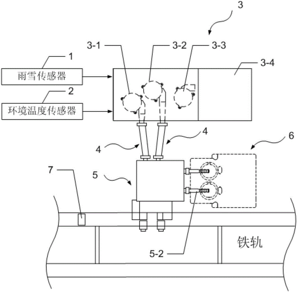
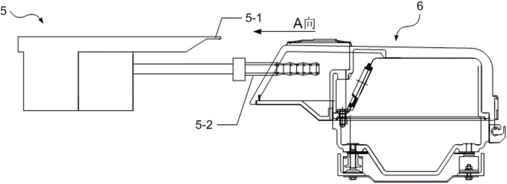
[0046] Specific implementation mode one: the following combination Figure 1 to Figure 6 Describe this embodiment, the snow or sundries removal system for train infrared shaft temperature detection equipment described in this embodiment includes a rain and snow sensor 1, an ambient temperature sensor 2, an air source mechanism 3, two air ducts 4 and an air box 5 ;
[0047] The air source mechanism 3 includes a box, and the box is provided with an external blower 3-1, an internal blower 3-2 and a controller 3-5;
[0048] The rain and snow signal output end of the rain and snow sensor 1 is connected with the rain and snow signal input end of the controller 3-5;
[0049] The ambient temperature signal output end of the ambient temperature sensor 2 is connected to the ambient temperature signal input end of the controller 3-5;
[0050] The internal snow removal start-stop command output end of the controller 3-5 is connected with the command input end of the internal blower 3-2;...
specific Embodiment approach 2
[0055] Specific implementation mode two: the following combination figure 1 and Figure 6 This embodiment will be described. The first embodiment will be further described in this embodiment, which also includes a passing vehicle detection sensor 7, which is used to detect whether there is a train passing by.
[0056] The vehicle passing detection sensor 7 is realized by a special axle counting sensor for railways.
[0057] The passing vehicle detection sensor 7 is arranged on the rail near the train infrared axle temperature detection device 6 .
specific Embodiment approach 3
[0058] Specific implementation mode three: the following combination figure 1 and Figure 6 Describe this embodiment, this embodiment will further explain Embodiment 1, one side wall of the box of the air source mechanism 3 is provided with an air inlet 3-4, and the inside of the box of the air source mechanism 3 also includes an air inlet fan 3-3 , the air outlet of the air inlet fan 3-3 faces the air inlet 3-4 of the air source mechanism 3, and the distance between the air inlet 3-4 and the air inlet 3-4 is greater than 80 mm; the controller 3-5 clears the air inlet start-stop command output The end is connected with the command input end of the air inlet fan 3-3.
[0059] In this embodiment, the distance between the air inlet 3-4 and the air inlet fan should be as large as possible under the condition of the air source mechanism box, so as to ensure the space at the air inlet and minimize the air intake affecting the air inlet. Under the premise, ensure that the air inlet...
PUM
 Abstract
Description
Claims
Application Information
 - R&D
- Intellectual Property
- Life Sciences
- Materials
- Tech Scout
- Unparalleled Data Quality
- Higher Quality Content
- 60% Fewer Hallucinations
Browse by: Latest US Patents, China's latest patents, Technical Efficacy Thesaurus, Application Domain, Technology Topic, Popular Technical Reports.
© 2025 PatSnap. All rights reserved.Legal|Privacy policy|Modern Slavery Act Transparency Statement|Sitemap|About US| Contact US: help@patsnap.com


