
System and method for removing snow or sundries for train infrared shaft temperature detection equipment

A technology for infrared shaft temperature and detection equipment, which is applied to cleaning methods, cleaning methods and appliances using gas flow, and shape measuring instruments for railway vehicles. , the effect of saving labor

Active Publication Date: 2018-02-16
HARBIN KEJIA GENERAL MECHANICAL & ELECTRICAL CO LTD
View PDF6 Cites 0 Cited by
  • Summary
  • Abstract
  • Description
  • Claims
  • Application Information

AI Technical Summary

Problems solved by technology

[0004] The purpose of the present invention is to solve the problem that the infrared shaft temperature detection equipment for measuring the train shaft temperature in snowy weather, because snow and sundries enter the detection window, affect the infrared detection optical path, and then affect the measurement accuracy. Snow or debris removal system for infrared shaft temperature detection equipment

Method used


Image

  • System and method for removing snow or sundries for train infrared shaft temperature detection equipment
  • System and method for removing snow or sundries for train infrared shaft temperature detection equipment
  • System and method for removing snow or sundries for train infrared shaft temperature detection equipment

Examples


specific Embodiment approach 1

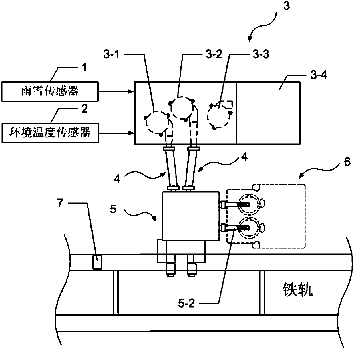
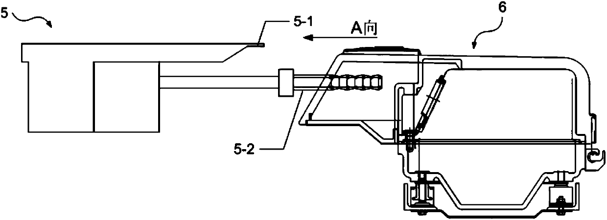
[0046] Specific implementation mode one: the following combination Figure 1 to Figure 6 Describe this embodiment, the snow or sundries removal system for train infrared shaft temperature detection equipment described in this embodiment includes a rain and snow sensor 1, an ambient temperature sensor 2, an air source mechanism 3, two air ducts 4 and an air box 5 ;

[0047] The air source mechanism 3 includes a box, and the box is provided with an external blower 3-1, an internal blower 3-2 and a controller 3-5;

[0048] The rain and snow signal output end of the rain and snow sensor 1 is connected with the rain and snow signal input end of the controller 3-5;

[0049] The ambient temperature signal output end of the ambient temperature sensor 2 is connected to the ambient temperature signal input end of the controller 3-5;

[0050] The internal snow removal start-stop command output end of the controller 3-5 is connected with the command input end of the internal blower 3-2;...

specific Embodiment approach 2

[0055] Specific implementation mode two: the following combination figure 1 and Figure 6 This embodiment will be described. The first embodiment will be further described in this embodiment, which also includes a passing vehicle detection sensor 7, which is used to detect whether there is a train passing by.

[0056] The vehicle passing detection sensor 7 is realized by a special axle counting sensor for railways.

[0057] The passing vehicle detection sensor 7 is arranged on the rail near the train infrared axle temperature detection device 6 .

specific Embodiment approach 3

[0058] Specific implementation mode three: the following combination figure 1 and Figure 6 Describe this embodiment, this embodiment will further explain Embodiment 1, one side wall of the box of the air source mechanism 3 is provided with an air inlet 3-4, and the inside of the box of the air source mechanism 3 also includes an air inlet fan 3-3 , the air outlet of the air inlet fan 3-3 faces the air inlet 3-4 of the air source mechanism 3, and the distance between the air inlet 3-4 and the air inlet 3-4 is greater than 80 mm; the controller 3-5 clears the air inlet start-stop command output The end is connected with the command input end of the air inlet fan 3-3.

[0059] In this embodiment, the distance between the air inlet 3-4 and the air inlet fan should be as large as possible under the condition of the air source mechanism box, so as to ensure the space at the air inlet and minimize the air intake affecting the air inlet. Under the premise, ensure that the air inlet...


PUM


Abstract

The invention provides a system and method for removing accumulated snow or sundries for train infrared axle temperature detecting equipment, and belongs to the field of railway assisted control systems. The problem that in severe snowing weather, due to the fact that snow and sundries enter a detection window, an infrared detection light path of the infrared axle temperature detecting equipment for measuring the train axle temperature is affected, and the measuring precision is affected accordingly can be solved. The system comprises a rain and snow sensor, an ambient temperature sensor, an air source mechanism, two air pipes and a bellows. The air source mechanism comprises a box, and an external air blower, an internal air blower and a controller are arranged in the box. Whether it snows can be accurately judged according to signals of the ambient temperature sensor and signals of the rain and snow sensor, and the air pipes are controlled to directly stretch into a train axle temperature measuring device to sweep the edge of a temperature measuring probe. The upper surface of the train axle temperature measuring device is swept again after delaying, the temperature measuring probe is prevented from being shielded by ice, snow and sundries on the surface again, and the temperature measuring precision is guaranteed.

Description

technical field [0001] The invention belongs to the field of railway auxiliary control systems. Background technique [0002] The shaft temperature of the train needs to be monitored online during operation. The commonly used detection equipment for the shaft temperature of the train is infrared shaft temperature detection equipment. The top of the equipment is equipped with an infrared detection window for temperature collection. In actual use, this kind of equipment will be arranged along the railway track, most of which are located in the field. This kind of equipment has fast measurement speed and high precision, but it will be affected by bad weather, especially in the north. When there is snow, the snow will block the detection window, which will affect or even hinder the measurement path of infrared rays, making the measurement inaccurate or even impossible. In addition, the snow in the north is often accompanied by strong winds, which will cause snow and even some d...

Claims


Application Information

Patent Timeline
Patent Type & Authority Patents(China)
IPC IPC(8): B61K9/04B08B5/02
CPCB08B5/02B61K9/04
Inventor 于海峰张广辉
Owner HARBIN KEJIA GENERAL MECHANICAL & ELECTRICAL CO LTD
Learn More