Arrangement structure of lattice-form underground continuous wall

An underground diaphragm wall and structure layout technology, which is applied to underwater structures, foundation structure engineering, sheet pile walls, etc., can solve the problems of difficult hoisting of steel cages, difficult processing of steel bars, and high project investment, so as to reduce construction risks , small amount of work, good overall performance

Active Publication Date: 2016-11-09
POWERCHINA CHENGDU ENG
View PDF5 Cites 1 Cited by
  • Summary
  • Abstract
  • Description
  • Claims
  • Application Information

AI Technical Summary

Problems solved by technology

The pile wall type is to arrange a pile body with a large cross-section at the junction of the vertical and horizontal walls, and arrange steel joints around the pile body as required, first construct the pile body, and then construct the surrounding "one"-shaped wall section; this structure Discretize the lattice-type underground continuous wall structure into piles and "one"-shaped walls. The hoisting of the cage is convenient, and it avoids the protruding corner of the covering layer that is easy to collapse at the junction of the longitudinal wall and the transverse wall; the disadvantage of this structure type is that the diameter of the pile body is much larger than the thickness of the wall body, and the project investme

Method used


Image

  • Arrangement structure of lattice-form underground continuous wall
  • Arrangement structure of lattice-form underground continuous wall
  • Arrangement structure of lattice-form underground continuous wall

Examples


Embodiment Construction

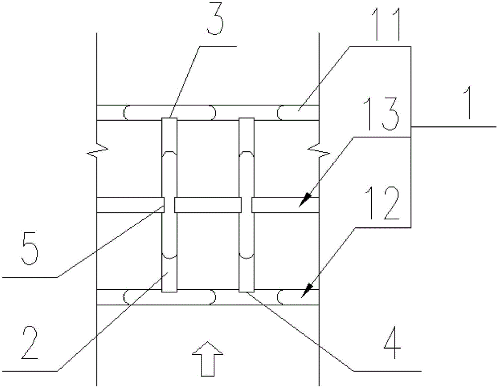
[0013] The present invention will be further described below in conjunction with the accompanying drawings, and the direction shown by the arrow in the figure is the main load direction.

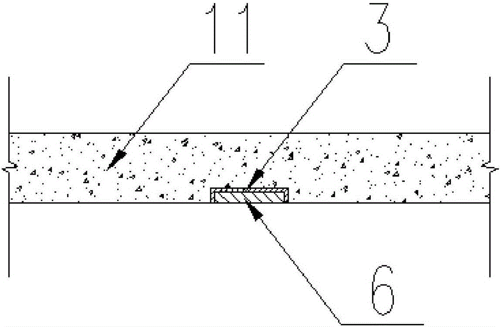
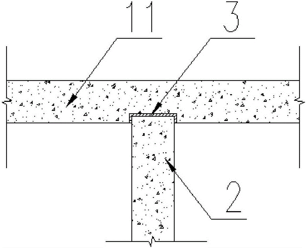
[0014] Such as figure 1 As shown, the present invention includes a longitudinal wall 1 and a transverse wall 2, the axis of the longitudinal wall 1 is perpendicular to the main load direction, the axis of the transverse wall 2 is the same as the main load direction, and the longitudinal wall 1 includes an inner longitudinal wall 11 and an outer longitudinal wall 12, One end of the transverse wall 2 is connected to the inner longitudinal wall 11, and the other end is connected to the outer longitudinal wall 12. The inner longitudinal wall 11 is provided with a U-shaped joint 3 on the side facing the outer longitudinal wall 12, and the U-shaped joint 3 is embedded in the inner longitudinal wall 11. And it is fixedly connected with the steel cage in the inner longitudinal wall 11, the end of th...


PUM


Abstract

The invention relates to an arrangement structure of a lattice-form underground continuous wall. The arrangement structure of the lattice-form underground continuous wall comprises longitudinal walls and transverse walls, wherein the axial lines of the longitudinal walls are perpendicular to a main load direction; the directions of the axial lines of the transverse walls are the same with the main load direction; the longitudinal walls comprise an inner-side longitudinal wall and an outer-side longitudinal wall; certain ends of the transverse walls are connected with the inner-side longitudinal wall, while the other ends of the transverse walls are connected with the outer-side longitudinal wall; one side, which faces to the outer-side longitudinal wall, of the inner-side longitudinal wall is provided with U-shaped joints; the U-shaped joints are embedded in the inner-side longitudinal wall, and are fixedly connected with a steel reinforcement cage in the inner-side longitudinal wall; the end parts of the transverse walls are embedded into groove bodies of the U-shaped joints; further, steel reinforcement cages in the transverse walls are fixedly connected with the U-shaped joints; one side, which faces to the inner-side longitudinal wall, of the outer-side longitudinal wall, is provided with second U-shaped joints; the second U-shaped joints are embedded into the outer-side longitudinal wall, and are fixedly connected with a steel reinforcement cage in the outer-side longitudinal wall; the end parts of the transverse walls are embedded into groove bodies of the second U-shaped joints; and further, the steel reinforcement cages in the transverse walls are fixedly connected with the second U-shaped joints.

Description

technical field [0001] The invention relates to a lattice-type underground continuous wall arrangement structure, which belongs to the fields of water conservancy and hydropower engineering and construction engineering. Background technique [0002] The underground diaphragm wall has the advantages of strong adaptability to geological conditions, good anti-seepage performance, high work efficiency, short construction period, reliable quality, high economic benefits, and small environmental impact. Currently, it is widely used as an anti-seepage structure in hydropower projects. It is mainly used as foundation pit protection structure in bridge and tunnel engineering. In water conservancy and hydropower projects, caissons are widely used as load-bearing and anti-scour structures, but their stability, economy, and construction difficulty are prominent. The defects of using caissons to deal with deep overburden foundations are very obvious. In view of the unique advantages of ...

Claims


Application Information

Patent Timeline
IPC IPC(8): E02D5/18E02D29/16
CPCE02D5/18E02D5/185E02D29/16E02D2300/0046
Inventor 孔科王小波汤雷雷运华相昆山
Owner POWERCHINA CHENGDU ENG
Why Eureka
Try Eureka