Automatic charging device and intelligent door lock including automatic charging device

A technology of automatic charging device and smart door lock, applied in circuit devices, battery circuit devices, components of connecting devices, etc., can solve problems such as restricting the rapid development of smart door locks, etc. Effect of contact area

Active Publication Date: 2016-11-09
田济民
5 Cites 3 Cited by

AI-Extracted Technical Summary

Problems solved by technology

[0002] Smart door locks with fingerprint recognition function, password function, remote control function and other functions are more and more popular among consumers because of their safety performance is much higher than that of traditional key door locks. However, it is necessary to support the operation of these functional modules Sufficient power supply must be ensured. The traditional power supply is provided by batteries. With such...

Method used

Please refer to Fig. 4 again, particularly, the first conductive fixed pin 144 is a screw, and the first gasket 146 is also provided between the positive contact block 142 and the first conductive fixed pin 144; the second conductive fixed pin 154 is Screws, a second gasket 156 is also provided between the negative electrode contact block 152 and the second conductive fixing pin 154 . After winding the power cord on the screw, put the washer on it and then screw the screw into the positive and negative contact blocks. Electricity. Gaskets are arranged between the positive and negative contact blocks and the conductive positioning pins, which effectively reduces the gap between the contact blocks and the positioning pins, resulting in a better fixing effect.
The ...

Abstract

The invention provides an automatic charging device and an intelligent door lock including the automatic charging device. The intelligent door lock comprises the automatic charging device, a door frame, a door body and a lock body; the automatic charging device includes an electric energy conveying part and an electric energy receiving part; the electric energy conveying part and the electric energy receiving part are respectively mounted on the door frame and the door body; and the lock body is provided with a rechargeable battery. The electric energy conveying part includes an electric energy conveying set, a first insulation positioning block and a first fixed frame arranged in sequence; the electric energy conveying set includes a positive pole conveying set and a negative pole conveying set; the electric energy receiving part includes an electric energy receiving set, a second insulation positioning block and a second fixed frame arranged in sequence; and the electric energy receiving set includes a positive pole receiving set and a negative pole receiving set. The designed intelligent door lock can easily realize automatic charging without adding redundant steps, and is high in charging electric energy conversion rate.

Application Domain

Technology Topic

Image

  • Automatic charging device and intelligent door lock including automatic charging device
  • Automatic charging device and intelligent door lock including automatic charging device
  • Automatic charging device and intelligent door lock including automatic charging device

Examples

  • Experimental program(1)

Example Embodiment

[0035] Example
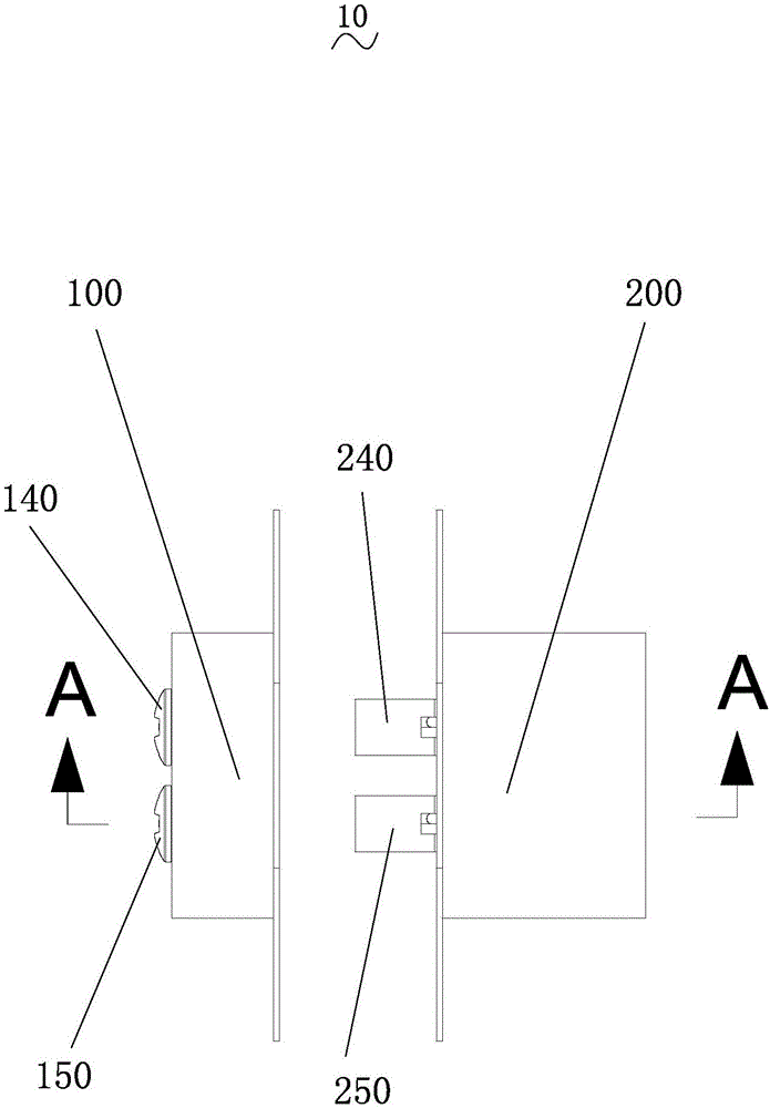
[0036] like figure 2 As shown, an automatic charging device 10 includes a power transmission part 100 and a power receiving part 200;
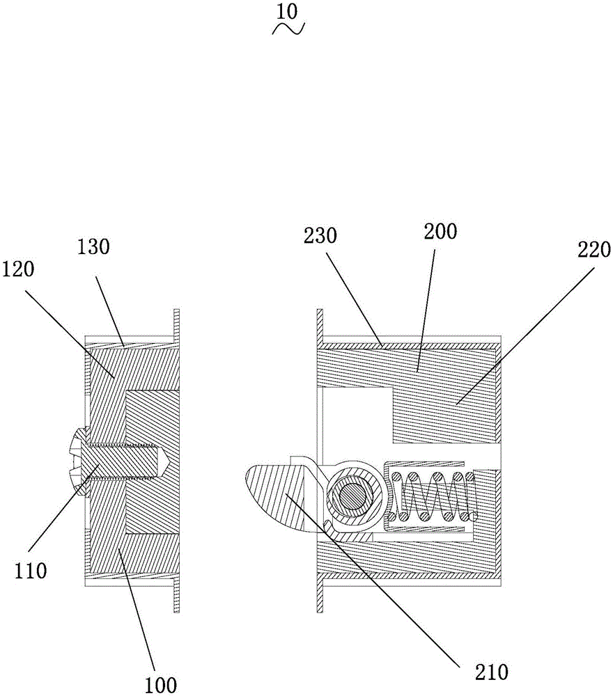
[0037] Please combine figure 2 , image 3 As shown, the power transmission unit 100 includes a power transmission group 110, a first insulating positioning block 120, and a first fixing frame 130 arranged in sequence. The power transmission group 110 includes a positive transmission group 140 and a negative transmission group 150. Please refer to Figure 4 The first insulating positioning block 120 is provided with two mutually independent first grooves 122 and second grooves 124 with an incomplete opening at the bottom, and the first fixing frame 130 is provided with a third groove 132 with an incomplete opening at the bottom , the first insulating positioning block 120 is accommodated in the third groove 132, the positive electrode transmission group 140 and the negative electrode transmission group 150 are respectively accommodated in the first groove 122 and the second groove 124, and pass through the first insulating positioning block 120 And pass through the first fixing frame 130 . The bottom of the groove of the first fixing bracket 130 is designed as an incomplete opening structure, so that when the first insulating positioning block 120 is accommodated inside, it will not slip out from the bottom of the groove. In addition, the first groove 122 and the second groove The slots 124 are designed to be independent of each other, so that no short circuit will be caused when the positive transmission group and the negative transmission group are accommodated.
[0038] see again figure 2 , image 3 , the power receiving unit 200 includes a power receiving group 210, a second insulating positioning block 220 and a second fixing frame 230 arranged in sequence, and the power receiving group 210 includes a positive receiving group 240 and a negative receiving group 250, please combine Figure 5As shown, the second insulating positioning block 220 is provided with two mutually independent first inner cavities 222 and second inner cavities 224 that are open at both ends, and the second fixing frame 230 is provided with a fourth groove 232 with an incomplete opening at the bottom. , the second insulating positioning block 220 is accommodated in the fourth groove 232, the positive electrode receiving group 240 and the negative electrode receiving group 250 are respectively accommodated in the first inner cavity 222 and the second inner cavity 224, and pass through the second insulating positioning block 220 And pass through the second fixing frame 230 . The bottom of the groove of the second fixing bracket 230 is designed as an incomplete opening structure, so that when the second insulating positioning block 220 is accommodated inside, it will not slip out from the bottom of the groove. In addition, the first inner cavity 222 and the second inner cavity The cavity 224 is designed as a structure independent of each other, so that it will not cause a short circuit when it is used for accommodating the positive transmission group and the negative transmission group.
[0039] Please combine figure 2 , image 3 , Figure 4 As shown, the positive electrode transmission group 140 includes a positive electrode contact block 142 and a first conductive fixing pin 144, and the positive electrode contact block 142 is fixed in the first groove 122 of the first insulating positioning block 120 by the first conductive fixing pin 144; The set 150 includes a negative electrode contact block 152 and a second conductive fixing pin 154 , and the negative electrode contact block 152 is fixed in the second groove 124 of the first insulating positioning block 120 through the second conductive fixing pin 154 . Here, the conductive fixing pin with conductive function is used instead of the insulating fixing pin. In addition to fixing the positive and negative contact blocks on the first insulating positioning block, it can also play the role of fixing the power line and conducting electricity.
[0040] see again Figure 4 , in particular, the first conductive fixing pin 144 is a screw, and a first gasket 146 is also provided between the positive contact block 142 and the first conductive fixing pin 144; the second conductive fixing pin 154 is a screw, and the negative contact block 152 and the first A second spacer 156 is also disposed between the two conductive fixing pins 154 . After winding the power cord on the screw, put the washer on it and then screw the screw into the positive and negative contact blocks. Electricity. Gaskets are arranged between the positive and negative contact blocks and the conductive positioning pins, which effectively reduces the gap between the contact blocks and the positioning pins, resulting in a better fixing effect.
[0041] Please combine figure 2 , image 3 , Figure 5 As shown, the positive receiving group 240 includes a first telescopic piece 242, a first conductive contact piece 244, and a first spring tongue 246 arranged in sequence; one end of the first telescopic piece 242 abuts on the first conductive contact piece 244, and the other end Butt against the second insulating positioning block 220; the first elastic tongue 246 is covered with a first insulating post 246a, and the first insulating post 246a is also covered with a first positioning piece 246b, and one end of the first positioning piece 246b is abutted against the first insulating post 246a. The other end of a spring tongue 246 abuts against the first conductive contact piece 244 .
[0042] The negative receiving group 250 includes a second telescopic piece 252, a second conductive contact piece 254, and a second elastic tongue 256 arranged in sequence; one end of the second telescopic piece 252 abuts against the second conductive contact piece 254, and the other end abuts against the second conductive contact piece 254. On the second insulating positioning block 220; the second elastic tongue 256 is covered with a second insulating column 256a, and the second insulating column 256a is also covered with a second positioning piece 256b, and one end of the second positioning piece 256b abuts against the second elastic tongue 256 , and the other end abuts against the second conductive contact piece 254 .
[0043] In order to make the locating member play a better positioning effect, a first spring tongue groove 246c is opened on the first spring tongue 246, and a second spring tongue groove 256c is opened on the second spring tongue 256. 246b and one end of the second positioning member 256b are actually respectively abutted in the first spring tongue groove 246c and the second spring tongue groove 256c. Also, in order to increase the strength of the insulating column, the first insulating pin 266 is used to insulate the first spring tongue groove. The column 246a and the second insulating column 256a are connected in series. The positioning piece, the conductive contact piece and the elastic tongue of the above positive and negative receiving groups can all conduct electricity, and one end of the conductive contact piece is connected to the power line 260. The pole receiving group and the power cord are passed to the device to be charged. Here, with the help of the resilience of the telescopic element itself, the elastic tongue can always stay in a suitable position, ensuring good contact effect between the elastic tongue and the positive and negative contact blocks.
[0044] See Figure 5 , in particular, the first telescopic member 242 and the second telescopic member 252 are springs.
[0045] The first locating piece 246b and the second locating piece 256b are locating springs whose cross-section is in the shape of a "Q". Good positioning effect.
[0046] see again Figure 5 In particular, the cross-sections of the first elastic tongue 246 and the second elastic tongue 256 are crescent-shaped, and the design of this structure is conducive to the expansion and contraction of the elastic tongues when opening and closing the door.
[0047] The cross-sections of the first conductive contact piece 244 and the second conductive contact piece 254 are in the shape of a "U", and the telescopic piece is packed into the recessed position of the conductive contact piece, which can better limit the direction of the telescopic movement of the flexible piece, and obtain a more ideal The expansion and contraction effect, but also increases the contact area of ​​the conductive contact piece, which is convenient for connecting the power line.
[0048] like figure 1 As shown, an intelligent door lock 20 includes the above-mentioned automatic charging device 10, and also includes a door frame 30, a door body 40, and a lock body 50. The power transmission part 100 and the power receiving part 200 are respectively installed on the door frame 30 and the door body 40. The lock body 50 has a rechargeable battery 52 connected to the power receiving part 200 . When the smart door lock 20 is in the closed state, the power transmission part 100 and the power reception part 200 are connected at this time, and the power is transmitted to the In the rechargeable battery 52, the purpose of automatic charging is realized. This charging method is simple and does not need to add redundant steps, and the conversion rate of charging electric energy is high.

PUM

no PUM

Description & Claims & Application Information

We can also present the details of the Description, Claims and Application information to help users get a comprehensive understanding of the technical details of the patent, such as background art, summary of invention, brief description of drawings, description of embodiments, and other original content. On the other hand, users can also determine the specific scope of protection of the technology through the list of claims; as well as understand the changes in the life cycle of the technology with the presentation of the patent timeline. Login to view more.

Similar technology patents

Power distribution network electrical equipment monitoring system

InactiveCN108508307AAvoid short circuitImprove securityTesting using acoustic measurementsTesting using optic methodsEmbedded systemCollections data
Owner:LANGFANG POWER SUPPLY COMPANY STATE GRID JIBEI ELECTRIC POWER COMPANY +1

Classification and recommendation of technical efficacy words

  • Avoid short circuit
  • Reduce gap

Delivery of protocol data units

Owner:NOKIA SOLUTIONS & NETWORKS OY
Why Eureka
Try Eureka