Low-pressure-loss underground tool for speeding up by vibration
A tool and low-pressure technology, which is applied in the field of downhole vibration speed-up tools with low pressure consumption, can solve the problems of high vibration frequency and short service life of tools, achieve the effects of small pressure loss, increase vibration effect, and avoid damage to downhole instruments
- Summary
- Abstract
- Description
- Claims
- Application Information
AI Technical Summary
Problems solved by technology
Method used
Image
Examples
Embodiment Construction
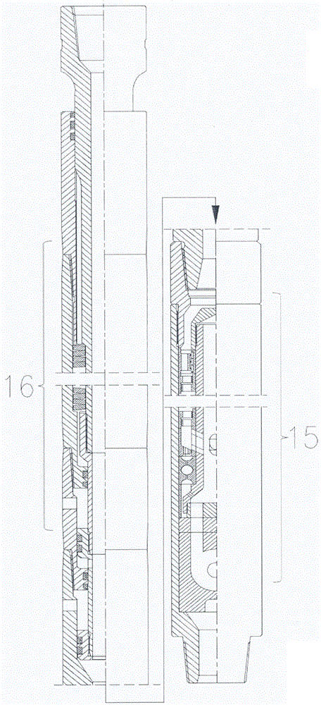
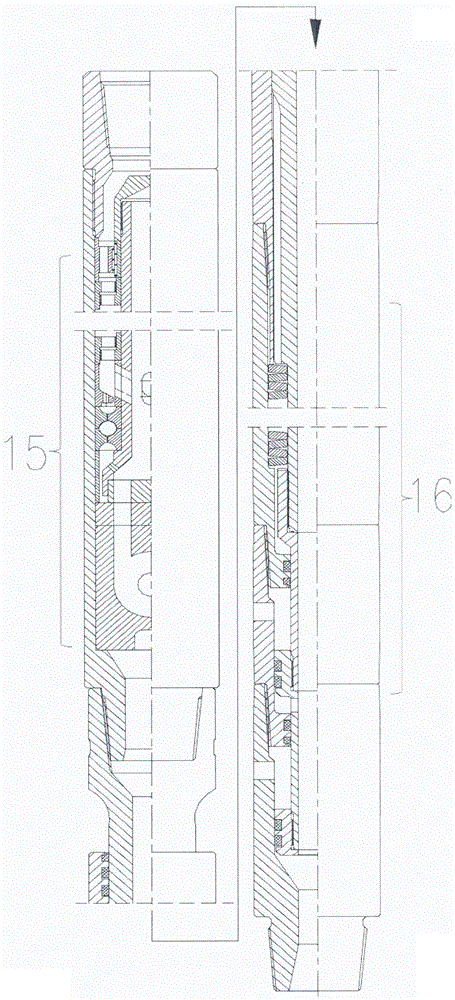
[0026] Such as Figure 1-2 中,一种低压耗井下振动提速工具,压力脉冲发生工具15和振幅放大工具16,压力脉冲发生工具15可以连接在振幅放大工具16的上部,也可以连接在振幅放大工具16的下部,参见 figure 1 , 2 middle.
[0027] Such as Figure 3-4 中,压力脉冲发生工具15的外壳体14内设有中心轴3,中心轴3可旋转的支承载外壳体14内,外壳体14和中心轴3设有驱动涡轮5,驱动涡轮5下部设有减速涡轮6,期驱动涡轮5和减速涡轮6的数量可为任意个数,可任意组合,使中心轴3转速可调,中心轴3下端与动阀片11固定连接,动阀片11下部设有定阀片12,动阀片11和定阀片12组成动、定阀组,动阀片11上设有动阀进液孔1101,动阀进液孔1101交替的与定阀片12的两进液孔1201连通,定阀片12的两进液孔1201与涡流振动装置13的两进液槽1301连通,定阀片12的下部设有成U型的涡流振动装置13,参见 image 3 .
[0028] 涡流振动装置13采用采用轴向对剖的结构,内设有成圆形的涡腔1302,两条进液槽1301与涡腔1302切向连接;涡腔1302的中心设有涡腔出口1303,涡腔出口1303与出液口1304连通,当高速液流由进液槽1301进入,在涡腔1302内形成涡流,参见 Figure 4 .
[0029] 当流体经上接头1进入工具内部,经成锥形的导流端盖2,引导流体流入中心轴3与外壳体14之间的间隙中,流经驱动涡轮5和减速涡轮6,驱动涡轮5带动中心轴3旋转,减速无聊6对中心轴3起减速作用,之后流体经导流环7流入中心轴3内部,经动阀片导流孔1101和定阀片导流孔1201进入涡流振动装置13,假设流体先进入涡流振动装置13的左进液槽1301,流体在涡腔1302内形成逆时针的涡流,动阀片11上部压力增加,处于压力脉冲的高压区,随着动阀片11的转动,液流切换到右进液槽1301,涡腔1302内的逆时针涡流开始消退,动阀片上部压力减小,处于压力脉冲的低压区,随着时间的推移,涡腔1302内顺时针涡流逐渐形成,动阀片11上部压力再次增加,处于压力脉冲高压区,如此反复,随着动阀片11的转动,在工具内形成周期性的压力波动。
[0030] Such as Figure ...
PUM
 Abstract
Description
Claims
Application Information
 - R&D
- Intellectual Property
- Life Sciences
- Materials
- Tech Scout
- Unparalleled Data Quality
- Higher Quality Content
- 60% Fewer Hallucinations
Browse by: Latest US Patents, China's latest patents, Technical Efficacy Thesaurus, Application Domain, Technology Topic, Popular Technical Reports.
© 2025 PatSnap. All rights reserved.Legal|Privacy policy|Modern Slavery Act Transparency Statement|Sitemap|About US| Contact US: help@patsnap.com


