Actuator having planetary roller screw

A technology of planetary roller and thread transmission, which is applied in the field of clutches to achieve the effect of high load capacity, reduced manufacturing and installation costs, and small moment of inertia

Active Publication Date: 2016-11-09
SCHAEFFLER TECH AG & CO KG
View PDF10 Cites 6 Cited by
  • Summary
  • Abstract
  • Description
  • Claims
  • Application Information

AI Technical Summary

Problems solved by technology

The disadvantage here is that axial forces from one direction can only be supported when only one ring gear rolling bearing is used

Method used


Image

  • Actuator having planetary roller screw
  • Actuator having planetary roller screw
  • Actuator having planetary roller screw

Examples


Embodiment Construction

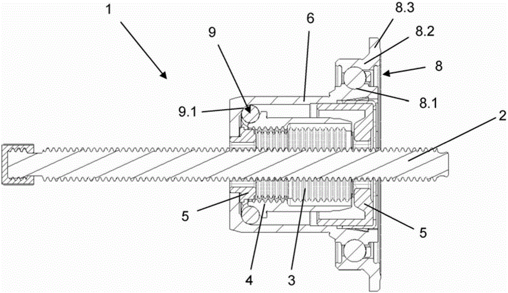
[0024] figure 1 A longitudinal section through a planetary roller screw drive according to the prior art is shown. The screw 2 is engaged by a plurality of planetary rollers 3 which mesh with a ring gear 4 surrounding the planetary rollers. The planetary rollers 3 are positioned at both ends in a planetary roller carrier 5 , which is mounted in a rotationally fixed manner in a sleeve 6 surrounding the ring gear 4 . The sleeve 6 and the planetary roller carrier 5 supported therein are fixed axially and are connected in a rotationally fixed manner via the sleeve 6 to a rotor (not shown) of the drive. The sleeve 6 is rotatably mounted via the main bearing 8 , wherein a bearing raceway 8 . 1 for the interior of the main bearing 8 is contained in the sleeve 6 . The bearing outer ring 8.2 of the main bearing 8 has a radially outwardly directed flange 8.3 for axial and rotationally fixed support on a not shown stator-side housing. The axial support of the planetary roller carrier ...


PUM


Abstract

The invention discloses an actuator having a planetary roller screw. The actuator is particularly intended for operating vehicle clutch and has a planetary roller screw (PWG). According to the invention, a plurality of planetary rollers engages a screw and engages a gear ring which encircles the planetary rollers. The planetary rollers are located at two end parts thereof on a planetary roller rack and are supported in a sleeve which encircles the gear ring in an anti-rotation manner. According to the invention, the gear ring is at least upported by one gear ring bearing. The gear ring bearing absorbs axial force in the direction of an operation stroke and the opposite directiont of the operation stroke.

Description

technical field [0001] The invention relates to an actuator with a planetary roller screw gear (PWG) and applies in particular to actuating a clutch of a vehicle. Background technique [0002] Planetary roller screw drives (PWG), also known as planetary roller screw drives or planetary roller screws, are known for a long time and are described, for example, in DD 0 277 308 A5. For example, a planetary roller screw drive is known from document DE 10 2010 047 800 A1, which is contained in a hydrostatic actuator in the form of a hydrostatic clutch actuator in order to convert a rotational movement generated by means of an electric motor into an axial sports. From the document DE 10 2010011 820 A1 a planetary roller screw drive is known, which has: a screw; a nut arranged on the screw; and a plurality of distributed over the circumference, arranged on the screw and the nut The planetary elements are arranged in a rolling manner on the inner circumference of the nut and on the ...

Claims


Application Information

Patent Timeline
IPC IPC(8): F16H25/22
CPCF16H25/2252F16D23/12F16D28/00F16H2025/2078
Inventor 拉斯洛·曼彼得·格雷布
Owner SCHAEFFLER TECH AG & CO KG
Why Eureka
Try Eureka