
LED energy-saving illuminator capable of removing dust automatically

A technology of LED energy-saving lamps and automatic dust removal, which is applied to lighting devices, fixed lighting devices, lighting and heating equipment, etc., can solve the problems of affecting the luminosity and the distance of irradiation, inability to adjust, and reduce brightness, and achieve reasonable structure and power saving. Effect

Active Publication Date: 2016-11-09
佛山市利升光电有限公司
View PDF6 Cites 6 Cited by
  • Summary
  • Abstract
  • Description
  • Claims
  • Application Information

AI Technical Summary

Problems solved by technology

[0002] 1. Lighting tubes are generally installed on the top or walls of higher buildings. After a period of use, there will be a layer of dust on the tubes. Due to the high installation of the tubes and the lack of dust or dust on the tubes on the ground Due to the limitation of cleaning tools, they generally do not clean or rarely do cleaning, and the dust accumulates more and more. After the dust covers, the brightness of the lighting decreases, which affects the luminosity and the distance of the irradiation; 2. There is only one switch for existing household and commercial lighting, no Adjust the brightness or only light up some of the LED lamp beads, which wastes more electricity when the brightness is not needed; 3. The existing LED lamp tube power-on control is either fully bright, or completely off after power off, when more brightness is needed Weak light or cannot be adjusted when night light is used

Method used


Image

  • LED energy-saving illuminator capable of removing dust automatically
  • LED energy-saving illuminator capable of removing dust automatically
  • LED energy-saving illuminator capable of removing dust automatically

Examples


Embodiment Construction

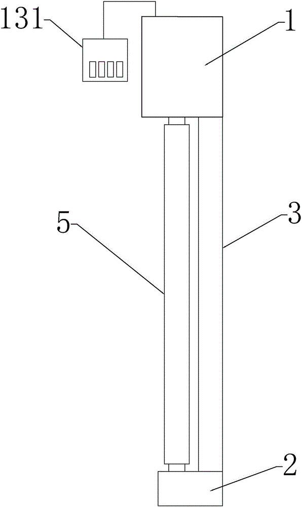
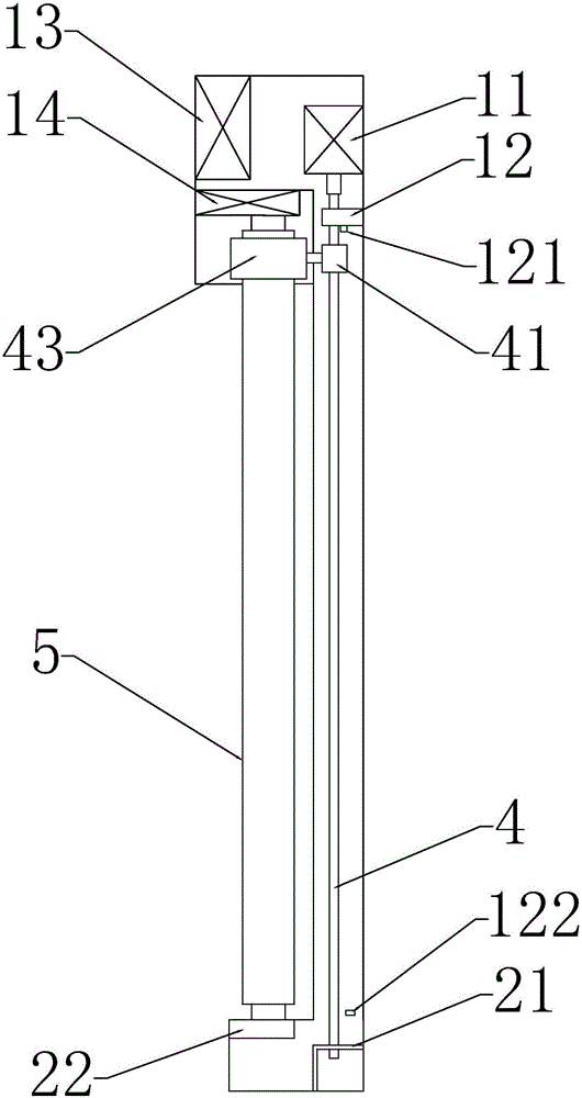
[0012] An LED energy-saving illuminator with automatic dust removal, the LED energy-saving illuminator includes a left end shell 1 and a right end shell 2, and a strip shell 3 is fixedly connected between the right end shell 2 and the left end shell 1; the left end shell A motor 11, a left threaded rotating shaft bracket 12, a controller 13, and a left lamp tube fixing joint 14 are fixed in the part 1; a right threaded rotating shaft bracket 21 and a right lamp tube fixing joint 22 are fixed in the right end shell part 2; Threaded shaft bracket 12 and right lamp tube fixed joint 22 are threaded shaft 4 in series, and one end of threaded shaft 4 is connected on the shaft of motor 11; Travel switch one 121 is fixed on the left threaded shaft bracket 12, close to the right end shell A travel switch 2 122 is fixed inside the end of the long shell 3 of 2; an LED energy-saving lamp 5 is fixed between the left lamp fixing joint 14 and the right lamp fixing joint 22; the top of the lon...


PUM


Abstract

The invention discloses an LED energy-saving illuminator capable of removing dust automatically. When normal illumination is required, illumination is controlled through a lamp tube stepless light-adjustment rotary switch. Luminance required for illumination is adjusted freely. A controller is internally provided with a motor work time-delay circuit module. When the dust needs to be removed, a motor switch is switched on; a motor rotates to work, and a threaded rotating shaft is driven to rotate, so that a rotating nut travels on the threaded rotating shaft; when touching a first travel switch or a second travel switch, the rotating nut moves back and forth automatically to perform the returning work; when the rotating nut travels, a circular ring body is driven to travel synchronously through a short connecting piece; the dust on an LED energy-saving lamp tube is scrapped off through a brush on the inner wall of the circular ring body, and automatic dust removal (lamp tube cleaning) is achieved; and after the dust is removed, original luminance is maintained. The lamp tube stepless light-adjustment rotary switch is used for adjusting the voltage of a power source, the required luminance is achieved by lowering the voltage, and electric quantity can be saved. When weak light is needed for illumination, a certain lamp bead or part of lamp beads are controlled to illuminate through a lamp bead switch, and electric quantity can be saved.

Description

technical field [0001] The invention relates to an energy-saving illuminator, in particular to an LED energy-saving illuminator with automatic dust removal. Background technique [0002] 1. Lighting tubes are generally installed on the top or walls of taller buildings. After a period of use, there will be a layer of dust on the tubes. Due to the high installation of the tubes and the fact that the tubes cannot be seen on the ground due to dust or Due to the limitation of cleaning tools, they generally do not clean or rarely do cleaning, and the dust accumulates more and more. After the dust covers, the brightness of the lighting decreases, which affects the luminosity and the distance of the irradiation; 2. There is only one switch for existing household and commercial lighting, no Adjust the brightness or only light up some of the LED lamp beads, which wastes more electricity when the brightness is not needed; 3. The existing LED lamp tube power-on control is either fully b...

Claims


Application Information

Patent Timeline
IPC IPC(8): F21S8/00F21V23/04B08B9/023F21Y115/10
CPCB08B9/023F21S8/00F21V23/04
Inventor 林永勤
Owner 佛山市利升光电有限公司
Learn More