Workshop heating system

A technology for heating systems and workshops, applied in heating systems, space heating and ventilation, household heating, etc., can solve the problems of easy scaling, rising operating costs, high costs, etc., and achieve simple manufacturing and reasonable design. , the effect of simple structure

Inactive Publication Date: 2016-11-09
天下石仓(天津)有限公司
View PDF7 Cites 0 Cited by
  • Summary
  • Abstract
  • Description
  • Claims
  • Application Information

AI Technical Summary

Problems solved by technology

[0003] This direct use of municipal water pipe heat source + radiator heating method is not only expensive but also has a large energy loss: the heating heat of municipal water pipe heat source + radiator heating method is mainly transmitted by convection, that is, the air must be heated first to make the moisture in the air heated The collision of air and water molecules will transfer the heat
In the central heating system, due to the small flow section of the plate heat exchanger and the low degree of turbulence, scaling and blockage are prone to occur: 1. The circulating water is heated and scaled to cause blockage. 2. Impurities enter the pipe network and cause blockage. 3. The inner wall of the pipe Rust, forming rust sludge and clogging
The main hazards caused are: 1. Significant increase in energy consumption and increase in operating costs 2. Decrease in system efficiency, affecting heating effect 3. Shorten the service life of equipment
In addition, because we are an industrial production and processing workshop, the gate of the workshop cannot be closed all day long because of the transfer of materials by forklifts and cranes. When the transfer vehicle enters and exits the workshop, the warm indoor air and the cold outside air immediately exchange heat, and the warm environment of the workshop immediately It will be destroyed, and the indoor temperature is not much different from the outdoor temperature, so it cannot satisfy the warming problem of the production personnel in the industrial plant in winter.

Method used


Image

  • Workshop heating system
  • Workshop heating system

Examples


Embodiment Construction

[0011] The specific implementation manner of the present invention will be described in detail below in conjunction with the accompanying drawings and preferred embodiments. In describing the present invention, it is to be understood that the terms "central", "longitudinal", "transverse", "front", "rear", "left", "right", "vertical", "horizontal", The orientations or positional relationships indicated by "top", "bottom", "inner", "outer", etc. are based on the orientations or positional relationships shown in the drawings, and are only for the convenience of describing the present invention and simplifying the description, rather than indicating or implying the It should not be construed as limiting the invention that a device or element must have a particular orientation, be constructed, and operate in a particular orientation.

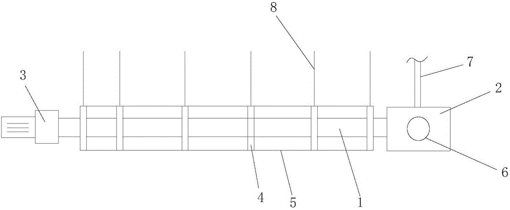
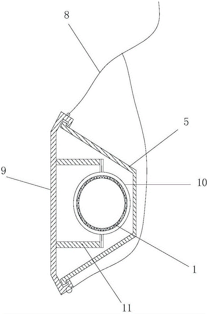
[0012] Such as figure 1 and figure 2 As shown, a workshop heating system includes an alloy tube 1, an electronic burner 2, a fan 3, an alloy tube...


PUM


Abstract

The invention relates to the field of heating equipment, in particular to a workshop heating system. The workshop heating system comprises an alloy pipe, an electronic burner, a fan, an alloy pipe fixed frame and a radiation cover; the electronic burner is mounted at one end of the alloy pipe, and is provided with a gas inlet pipe and a natural air inlet pipe; the fan is arranged at the other end of the alloy pipe; the alloy pipe is fixed in the radiation cover through the alloy pipe; and the radiation cover is fixed on a wall of a workshop through a hanging chain. The device is reasonable in design, simple in structure, convenient for manufacturing and low in cost. The thermal radiation heating has no boiler room, is more concentrated in heating, and can at least save thermal energy loss of heating power, outer nets and pipes in buildings by about 15-30%.

Description

technical field [0001] The invention relates to the field of heating equipment, in particular to a workshop heating system. Background technique [0002] The traditional municipal water pipe heat source heating method generally transports hot water from the heating company to the enterprise workshop through a dedicated municipal pipe network, and the enterprise installs a corresponding number of radiators in the factory building for heating. Compared with the heating effect of residential buildings with a floor height of about 3 meters, the heating effect of municipal water pipe heat source + radiator is good, economical and affordable, but the heating effect of industrial plants with a floor height of more than 3 meters is too ideal and the heating fee is the heating fee of residential buildings Calculated according to one heating season in the north, the cost of heating about 20,000 square meters of our industrial plant with municipal water pipe heat source + radiator heat...

Claims


Application Information

Patent Timeline
IPC IPC(8): F24D15/00F24D19/00
CPCF24D15/00F24D19/00F24D19/008
Inventor 陈万明
Owner 天下石仓(天津)有限公司
Why Eureka
Try Eureka