Electrocaloric refrigerator

A technology of refrigerators and electric cards, applied in refrigerators, refrigeration and liquefaction, machines using electric/magnetic effects, etc., can solve problems such as no refrigeration methods are given.

Inactive Publication Date: 2016-11-09
SHANGHAI UNIV OF ENG SCI
4 Cites 7 Cited by

AI-Extracted Technical Summary

Problems solved by technology

[0007] Although the aforementioned "Large Electric Card Effect in Ferroelectric Materials" describ...

Method used

Fig. 2 is the specific implementation figure of the present invention. The electric card refrigeration unit is composed of electric card material 1 , electrode material 2 and electrode material 3 . The electric card refrigeration unit is provided with a cooling fin 4 on o...

Abstract

The invention discloses an electrocaloric refrigerator. The electrocaloric refrigerator comprises a first electrocaloric material layer and an electrocaloric refrigeration unit composed of a first electrode layer and a second electrode layer attached to two sides of the first electrocaloric material layer, and further comprises a refrigeration piece located at one end of the electrocaloric refrigerator, a third electrode layer in tight contact with the refrigeration piece, a heat radiation piece located at the other end of the electrocaloric refrigerator, and a fourth electrode layer in tight contact with the heat radiation piece. The third electrode layer is opposite to the fourth electrode layer in position, and the third electrode layer is pointed at the electrocaloric refrigeration unit but makes no contact with the electrocaloric refrigeration unit. The electrocaloric refrigerator further comprises a track, pulse voltage is provided for the electrocaloric refrigerator by a power source, and a motor mechanically drives the electrocaloric refrigeration unit to reciprocate on the track so that the first electrode layer and the second electrode layer of the electrocaloric refrigeration unit can make contact with the fourth electrode layer on the heat radiation piece and the third electrode layer on the refrigeration piece correspondingly and alternatively.

Application Domain

Machines using electric/magnetic effectsSustainable buildings

Technology Topic

Pulse voltageHeat sink +4

Image

  • Electrocaloric refrigerator
  • Electrocaloric refrigerator
  • Electrocaloric refrigerator

Examples

  • Experimental program(1)

Example Embodiment

[0024] The technical solutions of the present invention will be clearly and completely described below in conjunction with the drawings in the embodiments of the present invention. The described example is only an example of the present invention, not all feasible implementations. Based on the same refrigeration principle, other design examples are all within the protection scope of the present invention.
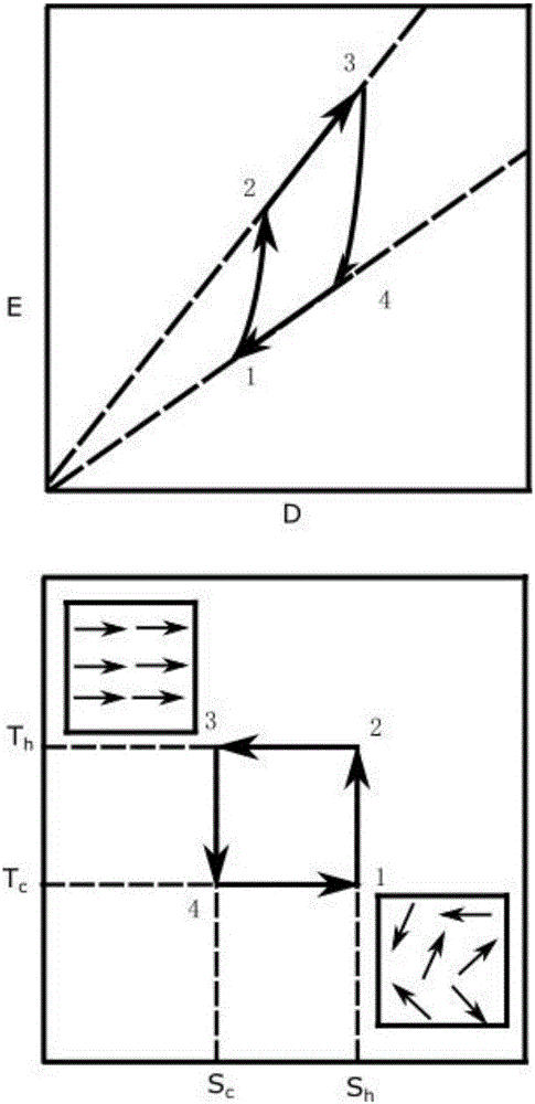
[0025] figure 1 Schematic diagram of the cooling effect of the electric card. The electric card refrigeration cycle goes through four steps at a time: (1) Voltage is applied to the electric card material without heat exchange with the outside, and the material system realizes the adiabatic heating process 1-2. Due to the electrical card effect, the material changes from state 1 (E 1 , T c , S h ) Changes to state 2 (E 2 , T h , S h ). (2) The voltage continues to increase. Material and constant temperature environment (T h ) Perform heat exchange, and the material system realizes an isothermal exothermic process 2-3. Material from State 2 (E 2 , T h , S h ) Changes to state 3 (E 3 , T h , S c ). (3) The voltage drops and the material does not exchange heat with the outside, the material system realizes adiabatic cooling process 3-4. Material from State 3 (E 3 , T h , S c ) Changes to state 4 (E 4 , T c , S c ). (4) The voltage continues to decrease and the material and constant temperature environment (T c ) Perform heat exchange, the material isotherm endothermic process 4-1. State 4 (E 4 , T c , S c ) Changes to state 1 (E 1 , T c , S h ). After one cycle, the material system returns to its original state. After one cycle, heat T is realized C The emission of ΔS.
[0026] figure 2 It is a specific implementation diagram of the present invention. The electric card refrigeration unit is composed of electric card material 1, electrode material 2 and electrode material 3. The electric card refrigeration unit is provided with cooling fins 4 on one side, and cooling fins 5 on the other side. The surfaces of the electrodes 6 and 7 that are in contact with the cooling fins 4 and the heat sink 5 are sputtered to form thin films of BeO or AlN materials to promote heat conduction and increase electrical insulation.
[0027] The electric card refrigeration unit is supplied with pulse voltage through the power supply 8 and mechanically driven by the motor 9 to move left and right on the track 10.
[0028] image 3 Middle 3-a is a schematic diagram of the relationship between the electric field and time in the electric card refrigeration unit after the electric card refrigeration unit is supplied with pulse voltage through the power supply 8 in the present invention; image 3 Middle 3-b is a schematic diagram of the relationship between displacement vector and time in the electric card refrigeration unit after the motor 9 provides mechanical movement to the electric card refrigeration unit. Such as image 3 As shown in 3-a, in phase 1, the electric card refrigeration unit moves to the heat sink, and the field changes from 0 to E 0; In stage 2, the electric card refrigeration unit contacts the heat sink to release heat; in stage 3, the electric card refrigeration unit separates from the heat sink and moves in the opposite direction to the left, and the electric field moves from E 0 Change to 0; In stage 4, the electric card refrigeration unit contacts the refrigeration sheet to absorb heat, restores to the initial state, and completes a cycle. After a reciprocating cycle, cooling is finally realized.

PUM

no PUM

Description & Claims & Application Information

We can also present the details of the Description, Claims and Application information to help users get a comprehensive understanding of the technical details of the patent, such as background art, summary of invention, brief description of drawings, description of embodiments, and other original content. On the other hand, users can also determine the specific scope of protection of the technology through the list of claims; as well as understand the changes in the life cycle of the technology with the presentation of the patent timeline. Login to view more.
Why Eureka
Try Eureka