Charging of batteries

a battery and charging technology, applied in the direction of battery/fuel cell control arrangement, electric devices, transportation and packaging, etc., can solve the problems of severe grid corrosion, high pulsed current amplitude and/or long pulsed charging time to charge the battery, and substantial heat and gas generation

Inactive Publication Date: 2000-11-28
COMMONWEALTH SCI & IND RES ORG
View PDF26 Cites 65 Cited by
  • Summary
  • Abstract
  • Description
  • Claims
  • Application Information

AI Technical Summary

Benefits of technology

FIG. 13 is a graph showing the effect of pulsed charging in accordance with the

Problems solved by technology

These methods have the disadvantage of requiring a high pulsed charging current amplitude and/or long pulsed charging time to charge the battery fully in the same time as it would take to charge the battery without the use of discharge pulses.
Furthermore, high pulsed current amplitude and long pulsed charging time lead to substantial heat and gas generation.
This may result in the drying out

Method used


Image

  • Charging of batteries
  • Charging of batteries
  • Charging of batteries

Examples


first embodiment

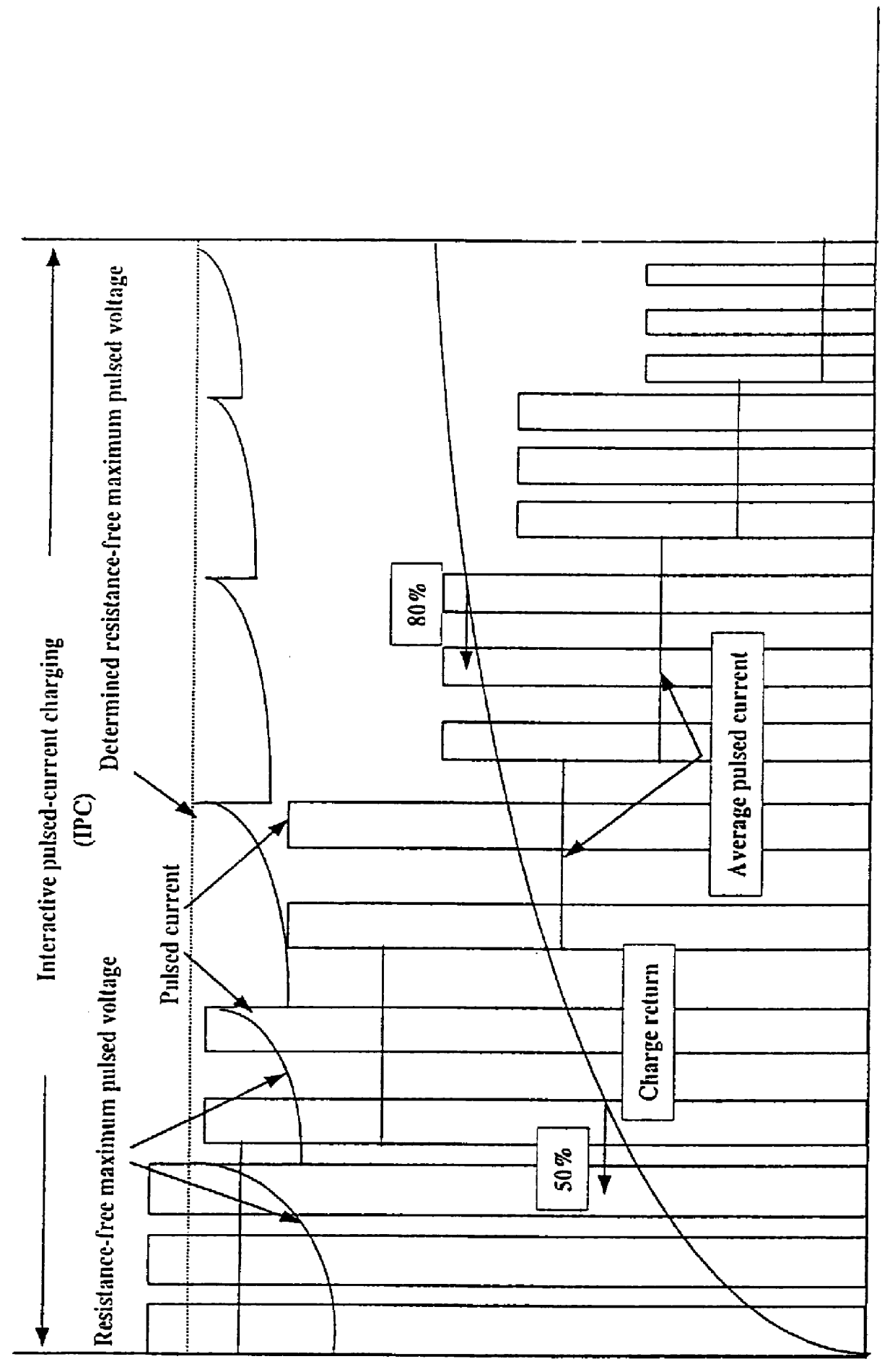
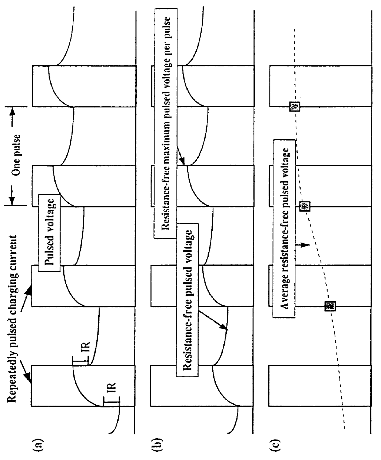
Referring firstly to the embodiment of FIG. 1 there is shown an example of repeatedly pulsed current charging according to a The method can be referred to as an interactive pulsed current (IPC method). A pulsed current is supplied to the battery which has a short ON-time, a high duty cycle and a high averaged pulsed current. For example, it is preferred that the ON-time is initially 20 ms, the duty cycle is initially 85% and the average pulsed current is initially about 6.5.times.C.sub.3 Amps (C.sub.3 being the 3 hour discharge capacity of the particular battery, such as a lead acid battery). During charging the average pulsed current will fall to about 0.02.times.C.sub.3 amps.

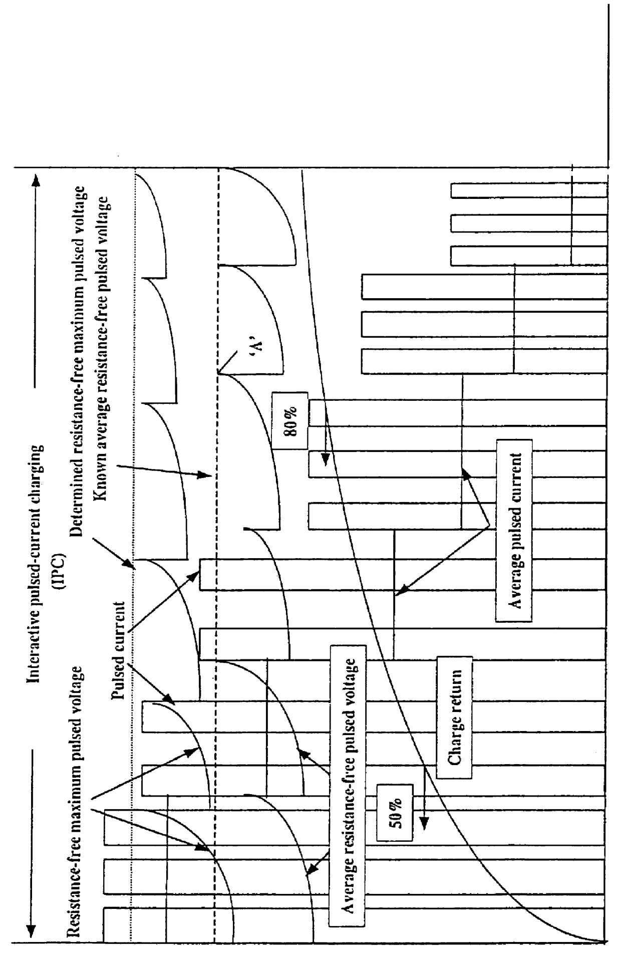
The amplitude of the pulsed current is controlled interactively to maintain the resistance free maximum pulsed voltage at the terminals of the battery above that of a known average resistance free pulsed voltage for the particular battery type.

The known average resistance free pulsed voltage for the battery t...

second embodiment

The process provides for enhanced battery charging and battery life relative to that in the first example.

Referring now to FIG. 4 there is shown a charging processes which embodies the concepts of the first and second examples as a first stage of charging (ie IPC) but other concepts in a second stage of charging. Here, the first stage of charging is represented by the embodiment of FIG. 1 or FIG. 3 and for convenience the first stage has been shown according to the embodiment of FIG. 3. It should be noted from FIG. 3 that the average pulsed charging current decreases over time during charging. This current is shown particularly where the resistance free maximum pulsed voltage has been maintained at the determined resistance free maximum pulsed voltage and indicated by character "B" in FIG. 4. When the repeatedly pulsed charging current falls to a particular level, the time taken to provide further appreciable charge will become unacceptable. In other words, to provide the balance o...


PUM


Abstract

A method and apparatus for fast charging of batteries such as lead acid batteries is provided. A repeatedly pulsed current is applied to the battery to enable a determined resistance free maximum pulsed voltage to be reached where the determined resistance free maximum pulsed voltage is below that at which unacceptable gassing will occur. The determined resistance free maximum pulsed voltage is above that of a known average resistance free pulsed voltage for the battery type. When the determined maximum pulsed voltage is reached the pulsed current is continued to be applied to maintain the resistance free maximum pulsed voltage at approximately the determined resistance free maximum pulsed voltage by at least one of: (I) reducing the amplitude of the pulsed charging current, (II) increasing the OFF-time of pulses of the pulsed charging current, (III) decreasing the ON-time of pulses of the pulsed charging current, (IV) a combination of any two or more of (I), (II) or (III). In addition, the present invention may employ a combination of stages to charge the battery. Alternatively or in combination, the system may use a repeatedly pulsed charging current or a repeatedly pulsed charge voltage to control and adjust the charging of the battery.

Description

The present invention relates to the charging of batteries, and relates particularly but not exclusively, to the fast pulse charging of lead acid batteries.DESCRIPTION OF PRIOR ARTDue to increasing urban pollution and limited fossil fuels, there is a need for road vehicles to meet strict emission requirements.Using present technology, zero-emission vehicles (ZEVs) are usually electrical vehicles (EVs) powered by batteries. In order to provide a competitive alternative, the EVs require high power high energy, and short charging "refuel" time for quick acceleration, and long distance travel, in a manner similar to standard internal combustion-engine vehicles. For practical purposes, the refuel charging times of the EVs have to be reduced from the present standard of many hours to the order of minutes whilst providing or even extending the service life of the batteries.Known methods of charging batteries include the use of pulsed currents using a combination of charge and discharge pul...

Claims


Application Information

Patent Timeline
IPC IPC(8): H02J7/00
CPCB60L3/0046B60L11/1816B60L11/185H02J7/0093B60L2230/16Y02T10/7005Y02T10/7088Y02T90/121Y02T90/128Y02T90/14Y02T90/163Y02T10/7016B60L53/14B60L53/11B60L53/305H02J7/00711B60L58/16Y02T10/70Y02T10/7072Y02T90/12Y02T90/16
Inventor LAM, LAN TWILSON, NICHOLAS CPHYLAND, CHRISTOPHER G
Owner COMMONWEALTH SCI & IND RES ORG
Why Eureka
Try Eureka