Touch panel

a technology of touch panel and electrode, applied in the field of touch panel, can solve problems such as errors, and achieve the effect of reducing electrode deterioration and being highly reliabl

Inactive Publication Date: 2012-06-14
OPTREX CORP
View PDF4 Cites 57 Cited by
  • Summary
  • Abstract
  • Description
  • Claims
  • Application Information

AI Technical Summary

Benefits of technology

[0059]In accordance with the present invention, it is possible to provide a

Problems solved by technology

For this reason, if plural positions are touched by e.g. a fingertip or fingertips,

Method used


Image

  • Touch panel
  • Touch panel
  • Touch panel

Examples


first embodiment

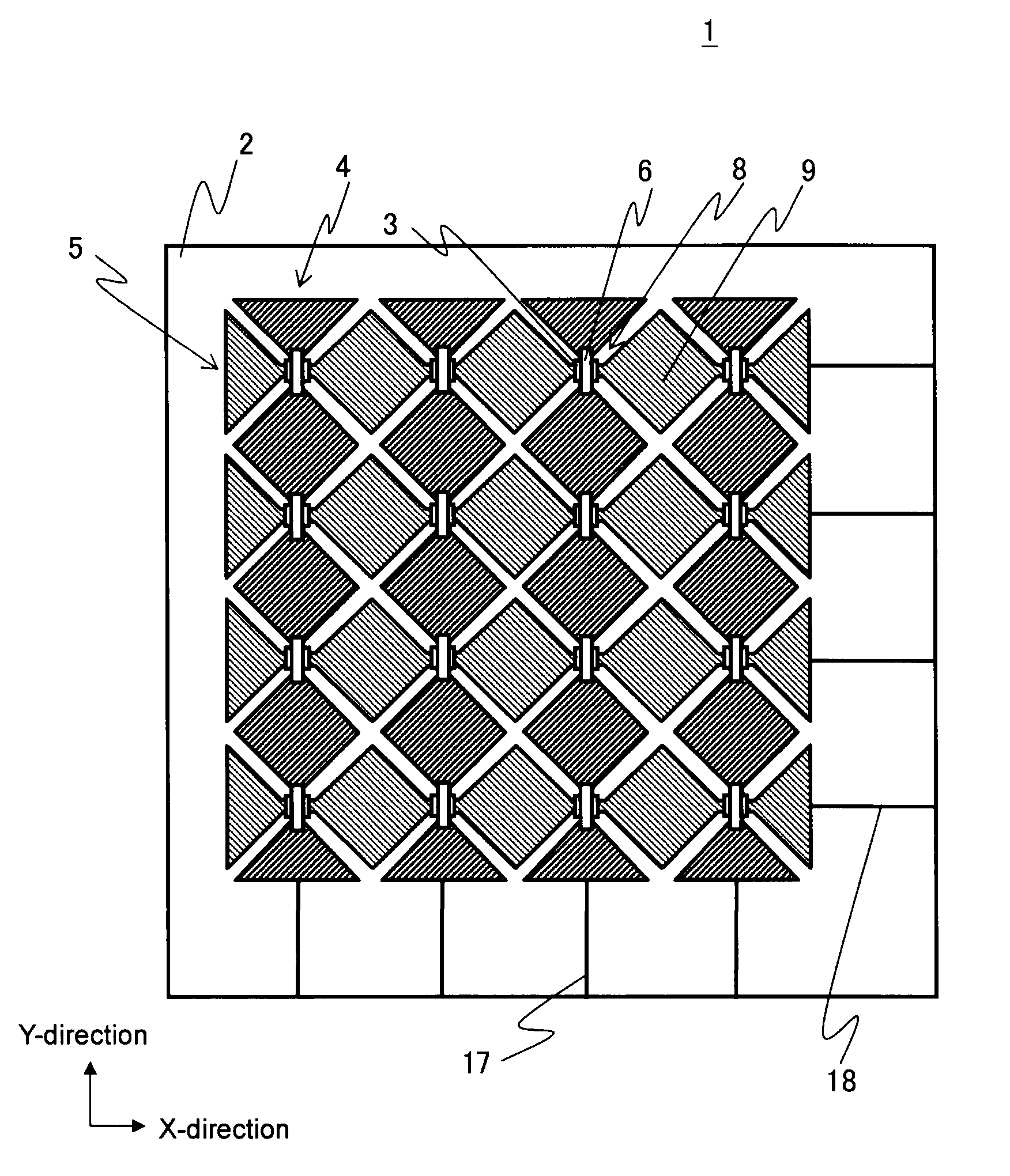
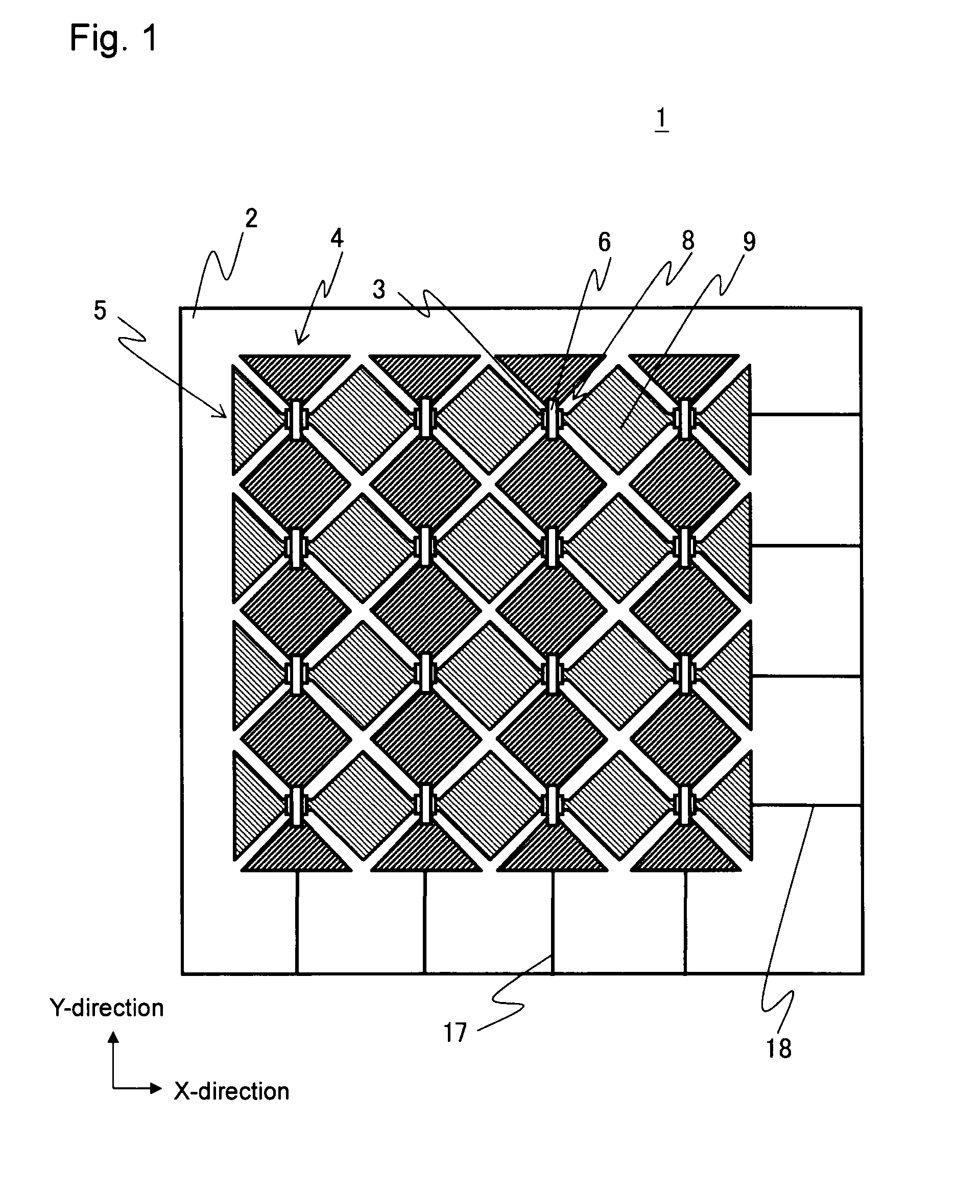
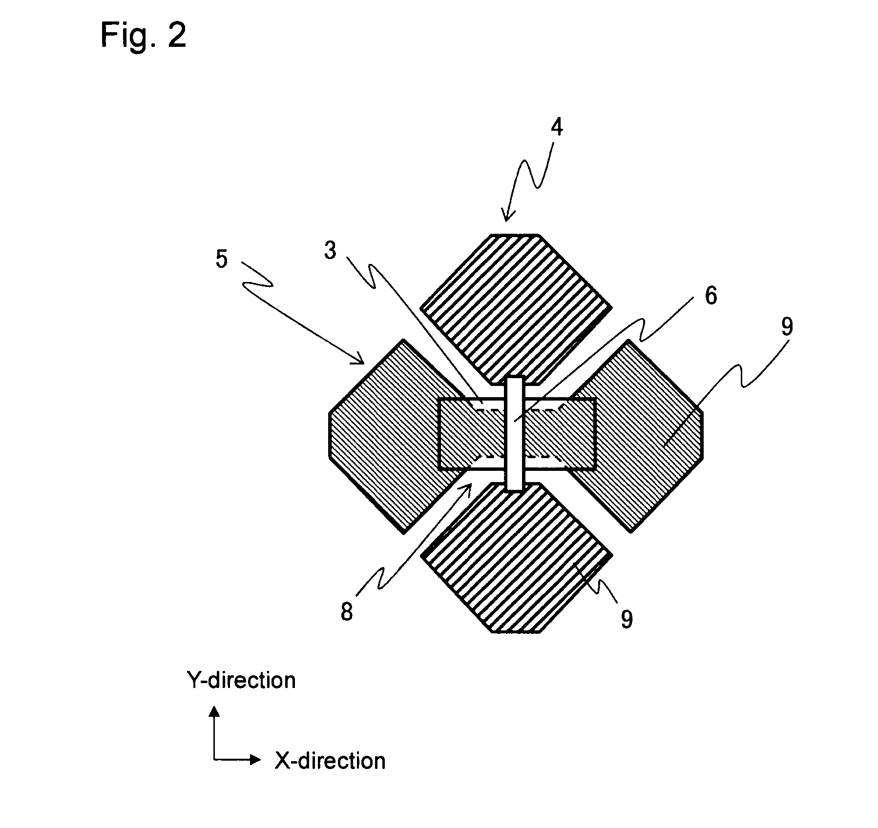
[0079]FIG. 1 is a plan view explaining a schematic structure of the tough panel according to a first embodiment of the present invention.

[0080]The touch panel 1 shown in FIG. 1 has a plurality of first electrodes 4 and a plurality of second electrodes 5 disposed on one side of a transparent substrate 2 as a light-transmitting substrate.

[0081]The transparent substrate 2 is an electrically insulating substrate, which may be, for example, a glass substrate, a PET (polyethylene terephthalate) film or a PC (polycarbonate) film. When the transparent substrate is a glass substrate, the transparent substrate may have a thickness of 0.3 mm to 3.0 mm.

[0082]The first electrodes 4 and the second electrodes 5 are all similar light-transmitting electrodes (hereinbelow, also referred to as the transparent electrodes) and are disposed on an area working as the operation screen of the touch panel 1. The first electrodes 4 and the second electrodes 5 are constituted by a transparent material, which h...

second embodiment

[0112]FIG. 6 is a view showing the structure of the touch panel according to a second embodiment of the present invention.

[0113]In the touch panel 100 as another example shown in FIG. 6, first electrodes 104, lead-out wires 117, which extend in the Y-direction, form sensing lines 121. Second electrodes 105 and lead-out wires 118, which extend in the X-direction, form drive lines 122.

[0114]As shown in FIG. 6, the first electrodes 104 are patterned so as to connect between adjacent electrodes at each of crossing portions 108 where the first electrodes 104 and the second electrodes 105 cross each other. On the other hand, the second electrodes 105 are patterned so as to be interrupted between adjacent electrodes at each of the crossing portions 108. In other words, the first electrodes 104 are electrically connected between adjacent electrodes, while the second electrodes 105 are interrupted between adjacent electrodes. The electrical connection between the interrupted portions of the ...

third embodiment

[0130]In the touch panel according to the present invention, it becomes possible to constitute the sensing lines and the drive lines by the same material by optimizing the relationship between the VDL of the pulse voltage applied to the drive lines and the VS applied to the sensing lines. It is possible to provide the touch panel according to a third embodiment, which includes the sensing lines and the drive lines constituted by the same material and has the similar structure as the above-mentioned embodiments in terms of the other structure.

[0131]FIG. 9 is a schematic view showing the relationship between a low potential of the drive lines and the potential of the sensing lines in the touch panel according to the third embodiment.

[0132]Specifically, in the above-mentioned touch panel according to the third embodiment, the bridge electrodes may be constituted by a transparent conductive material selected from ITO, IZO and ZnO. The sensing lines and the drive lines, which cross each ...


PUM


Abstract

A capacitive touch panel has a plurality of first transparent electrodes and a plurality of second transparent electrodes on a transparent substrate. At crossing portions between the first and second electrodes, adjacent electrodes of the second electrodes have no interruption, and adjacent electrodes of the first electrodes are interrupted. An interlayer insulating film is disposed as an upper layer on the second electrodes, and a bridge electrode is disposed as an upper layer on the interlayer insulating film to connect interrupted portions of the first electrodes at the crossing portions. The material constituting the bridge electrode contains an element that is more susceptible to oxidation than elements contained in a material constituting the second electrodes. Constant voltage is applied to the first electrodes, and a pulse voltage having a low potential equal to or higher than the potential of the first electrodes is applied to the second electrodes.

Description

BACKGROUND OF INVENTION[0001]1. Field of Invention[0002]The present invention relates to a touch panel.[0003]2. Discussion of Background[0004]Electronic devices, such as a cellular telephone, a smart phone and a PDA (personal digital assistant), have a limited area for placing an input unit, such as a switch or a digital keypad, since they are required to have a large screen. Further, it is required to realize information input measures wherein a user can input information in an easy-to-understand manner by touching a display image while seeing an image displayed on a display element, such as a liquid crystal display.[0005]Thus, a demand to provide a display with a touch panel has recently increased.[0006]A touch panel is placed on a display element, such as the above-mentioned liquid crystal display, and is a generic term of input units, which detect where a touch is made, when a user touches an operation screen by his or her finger, a pen or the like. The system for detecting wher...

Claims


Application Information

Patent Timeline
IPC IPC(8): G06F3/045
CPCG06F2203/04111G06F3/044G06F3/0446G06F3/0443
Inventor KAMOSHIDA, KENTAWATANABE, KIYOSHI
Owner OPTREX CORP
Why Eureka
Try Eureka