Copious cooling liquefied air energy storage method and system coupled with solar-thermal technology

A technology that couples solar energy and energy storage systems, applied in the field of energy storage of Air Liquide, can solve the problems of environmental pollution and high operating costs, achieve the effect of low collection and transportation costs, and increase the gasification rate

Inactive Publication Date: 2016-11-09
GLOBAL ENERGY INTERCONNECTION RES INST CO LTD +1
View PDF7 Cites 1 Cited by
  • Summary
  • Abstract
  • Description
  • Claims
  • Application Information

AI Technical Summary

Problems solved by technology

[0004] Therefore, the technical problem to be solved by the present invention is to overcome the technical defects of hig

Method used


Image

  • Copious cooling liquefied air energy storage method and system coupled with solar-thermal technology

Examples


Embodiment 1

[0040] This embodiment provides an energy storage method for cryogenic liquefied air, comprising the following steps:

[0041] Step 1: Using electric energy to convert gaseous air into liquid air under low temperature and high pressure conditions, and collecting the liquid air, collecting heat energy released during the conversion process, and the collected heat energy is used to provide high temperature conditions for step 2;

[0042] Step 2: converting the collected liquid air into gaseous air under high temperature and high pressure conditions, and collecting the cold energy released during the conversion process, and the collected cold energy is used to provide low temperature conditions for step 1;

[0043] Step 3: Collecting and storing solar heat, using the solar heat and the heat energy collected in step 1 to provide high temperature conditions for step 2.

[0044] The above-mentioned implementation mode is the core technical solution of this embodiment, by collecting ...

Embodiment 2

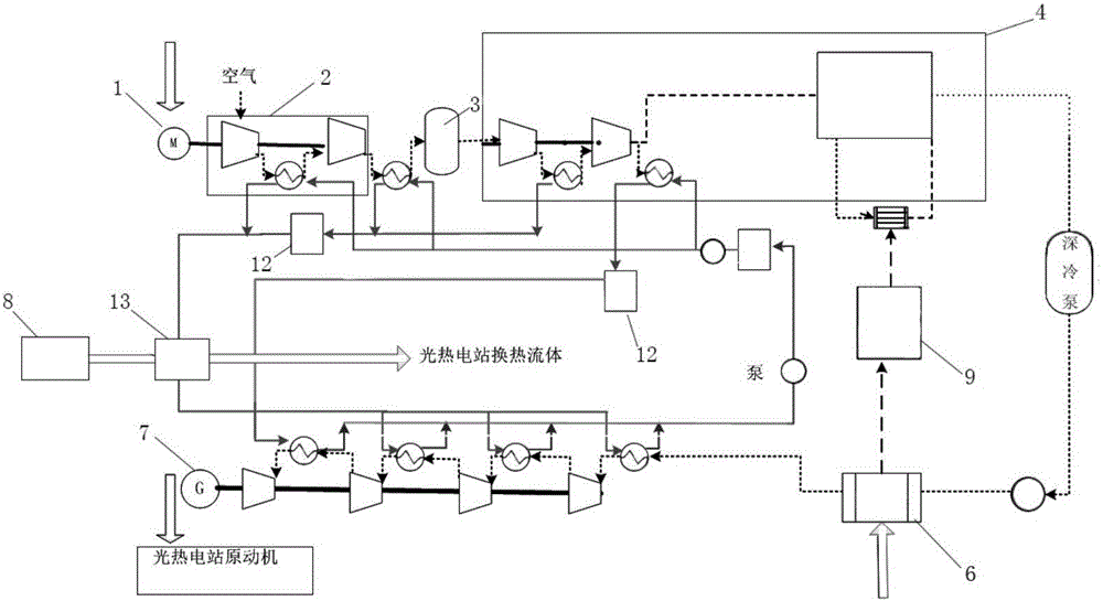
[0050] This embodiment provides a photothermal energy storage power generation system, the following combination figure 1 The energy storage system of this embodiment is described in detail:

[0051] The photothermal energy storage power generation system of this embodiment includes:

[0052] The energy input device 1, that is, the motor, converts electrical energy into mechanical energy and drives the first air compression device 2 and the second air compression device 4 to do work, wherein the first air compression device 2 is a low-pressure compressor; the second air compression device 4 is High pressure compressor. Specifically, the first air compression device 2 performs primary compression on the gaseous air driven by the energy input device 1. At this time, the air compressed by the primary stage is still in a gaseous state, and then the gas compressed by the primary stage is purified by the air purification device 3. Then carry out secondary compression, the second a...


PUM


Abstract

The invention provides a copious cooling liquefied air energy storage method and system coupled with the solar-thermal technology. The method includes the following steps that first, gaseous air is converted into liquefied air through electric energy under the low-temperature and high-pressure condition, the liquefied air and heat energy released in the conversion process are collected, and the collected heat energy is used for providing a high-temperature condition for the second step; second, the collected liquefied air is converted into gaseous air under the high-temperature and high-pressure condition, cold energy released in the conversion process is collected, and the collected cold energy is used for providing the low-temperature condition for the first step; and third, solar thermal is collected and stored, and the solar thermal and the heat energy collected in the first step are used for providing the high-temperature condition for the second step together.

Description

technical field [0001] The invention relates to the technical field of energy storage of liquefied air, in particular to an energy storage method of coupling photothermal energy with cryogenic liquid air and a photothermal energy storage power generation system. Background technique [0002] Cryogenic liquefied air energy storage technology refers to the use of electric energy for compressed air during the low load period of the grid, and the high-pressure sealing of the air in abandoned mines, subsidence subsea gas storage tanks, caves, expired oil and gas wells or newly built gas storage wells. The energy storage method releases compressed air during the peak period to drive the steam turbine to generate electricity. The liquid air energy storage system has the advantages of large energy storage capacity, long energy storage period, small footprint and does not depend on geographical conditions. During energy storage, the electric energy compresses, cools and liquefies the...

Claims


Application Information

Patent Timeline
IPC IPC(8): F25J5/00F28D20/00F25B43/00F24J2/00
CPCF24S21/00F25B43/006F25J5/00F28D20/00F28D2020/0065Y02E10/40Y02E60/14Y02E70/30
Inventor 徐桂芝赵波杨岑玉王乐宋洁金翼邓占锋胡晓汤广福宋鹏翔李志远梁立晓
Owner GLOBAL ENERGY INTERCONNECTION RES INST CO LTD
Why Eureka
Try Eureka