Blade tip gap measuring system and method based on AC discharging

A technology of blade tip clearance and AC discharge, applied in the field of blade clearance measurement, can solve the problems of friction between blade tip and inner wall of casing, affecting engine safety, and damage to parts and so on.

Inactive Publication Date: 2016-11-09
NANJING UNIV OF AERONAUTICS & ASTRONAUTICS
View PDF6 Cites 14 Cited by
  • Summary
  • Abstract
  • Description
  • Claims
  • Application Information

AI Technical Summary

Problems solved by technology

However, if the blade tip clearance is too small, due to the expansion of the blade due to heating in a high temperature environment, it ma

Method used


Image

  • Blade tip gap measuring system and method based on AC discharging
  • Blade tip gap measuring system and method based on AC discharging
  • Blade tip gap measuring system and method based on AC discharging

Examples


Example Embodiment

[0026] The technical solution of the present invention will be described in detail below in conjunction with the accompanying drawings.

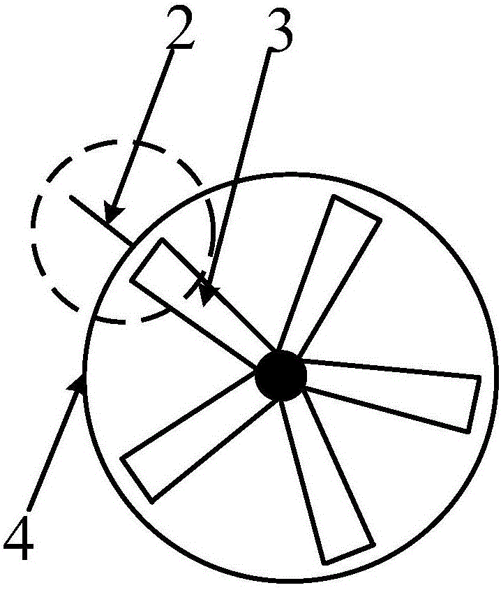
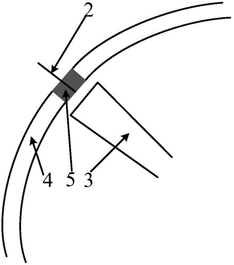
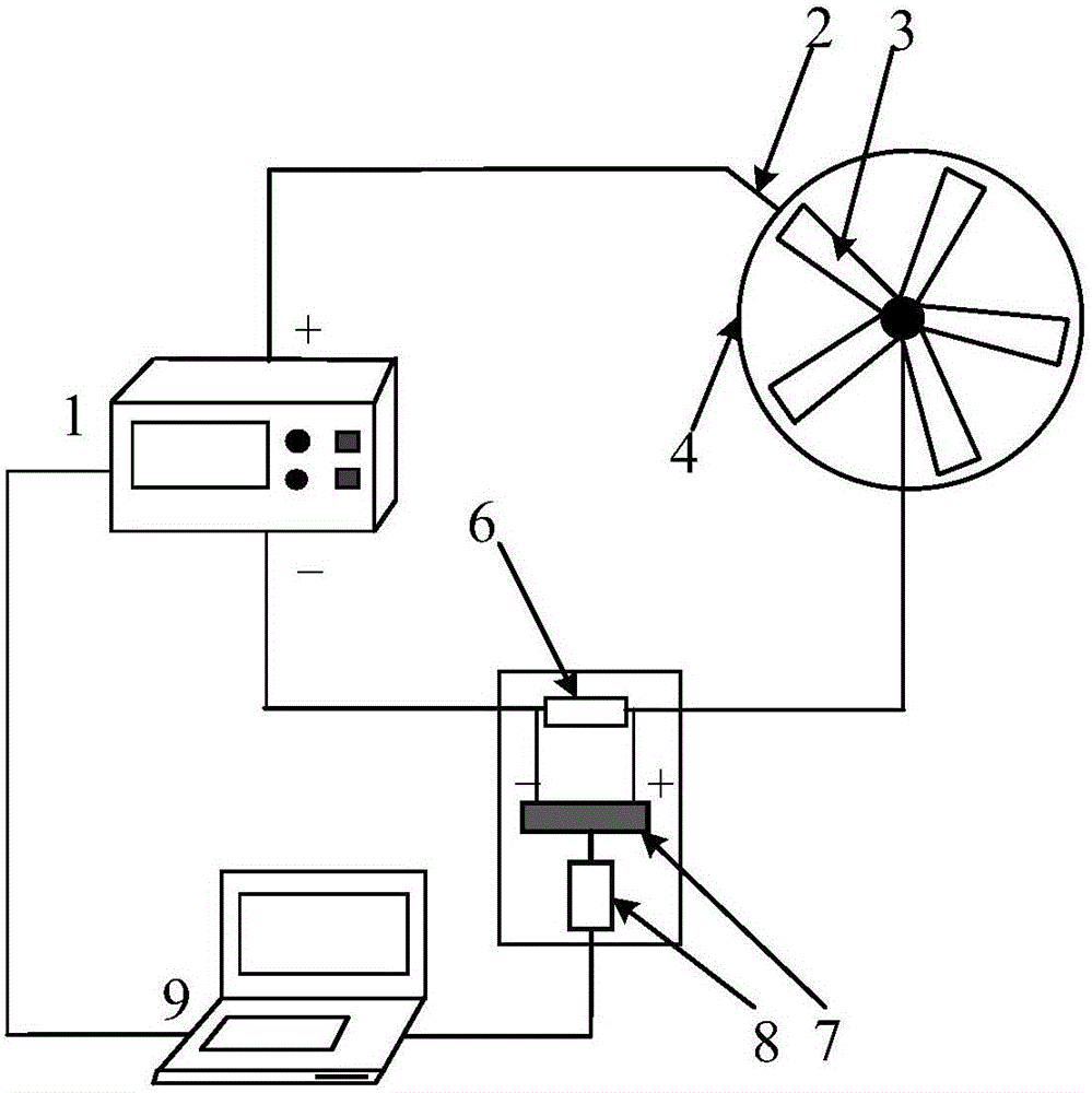
[0027] Such as image 3 As shown, the present invention provides a blade tip gap measurement system based on AC discharge, including AC numerically controlled adjustable excitation 1, discharge probe 2, detection resistor 6, voltage sensor 7, analog-to-digital converter 8, and data processing module 9. Among them, the discharge probe 2 is inserted into the receiver 4 from the outside of the receiver 4 to cooperate figure 1 with figure 2 As shown, one end of the discharge probe 2 is flush with the inner wall of the casing 4, and the other end is exposed outside the casing 4, and the part where the discharge probe 2 is inserted into the casing 4 is wrapped with an insulating layer 5, The discharge probe 2 is completely isolated from the receiver 4; the high voltage end of the AC numerically controlled adjustable excitation 1 is connected to the d...


PUM


Abstract

The invention discloses a blade tip gap measuring system based on AC discharging. The blade tip gap measuring system comprises an AC numerical control adjustable exciter, a discharging probe, a current measurement conversion module, and a data processing module. One end of the discharging probe is flush with the inner wall of a casing. The other end of the discharging probe is exposed outside the casing. The part, inserted into the casing, of the discharging probe is wrapped in an insulated layer. The high-voltage end of the AC numerical control adjustable exciter is connected with the discharging probe. The cathode of the AC numerical control adjustable exciter is connected with the center of a rotor blade via the current measurement conversion module. The current measurement conversion module is connected with the control end of the AC numerical control adjustable exciter via the data processing module and is used for controlling the amplitude and the output of the output voltage of the AC numerical control adjustable exciter. A measuring method comprises drawing a relation curve between discharging initial voltage and blade tip gaps, measuring the discharging initial voltage of a rotor blade to be measured, finding out a corresponding blade tip gap value according to the relation curve, namely the blade tip gap of the rotor to be measured. The blade tip gap measuring system is good in practicality, convenient to install and use, simple in operation, short in voltage regulation time, and high in efficiency.

Description

technical field [0001] The invention belongs to the field of blade clearance measurement, in particular to a blade tip clearance measurement system and method based on AC discharge. Background technique [0002] Aeroengine radial clearance measurement, especially high-pressure turbine clearance measurement, has always been a worldwide testing problem. Aeroengine blade tip radial clearance refers to the distance between the blade tips of the rotor blades of each stage of the engine and the engine casing, which is one of the important parameters affecting the performance of the aeroengine. When the radial gap between the engine rotor tip and the inner wall of the casing is too large, the pressure ratio of the compressor will decrease, the fuel consumption will increase, and the efficiency of the engine will also be greatly reduced. British R·R company's research on modern gas turbine engines shows that for every 1% increase in blade tip clearance, the efficiency will decrease...

Claims


Application Information

Patent Timeline
IPC IPC(8): G01B7/14
CPCG01B7/14
Inventor 于兵王继强申恩玉胡宗志袁培
Owner NANJING UNIV OF AERONAUTICS & ASTRONAUTICS
Why Eureka
Try Eureka