Bulb tube and operating method therefor

A working method and tube technology, which are applied to the components of the X-ray tube, the structural circuit components of the X-ray tube, etc., can solve the problem that the tube cannot independently save information, etc., to improve user experience, convenient maintenance, and maintenance. handy effect

Active Publication Date: 2016-11-09
SHANGHAI UNITED IMAGING HEALTHCARE
View PDF7 Cites 4 Cited by
  • Summary
  • Abstract
  • Description
  • Claims
  • Application Information

AI Technical Summary

Problems solved by technology

[0007] The present invention solves the problem that the existing ball tube needs to manually enter the basic information, and the problem that the information cannot be saved independently when the ball tube fails or is replaced

Method used


Image

  • Bulb tube and operating method therefor
  • Bulb tube and operating method therefor
  • Bulb tube and operating method therefor

Examples


Embodiment 1

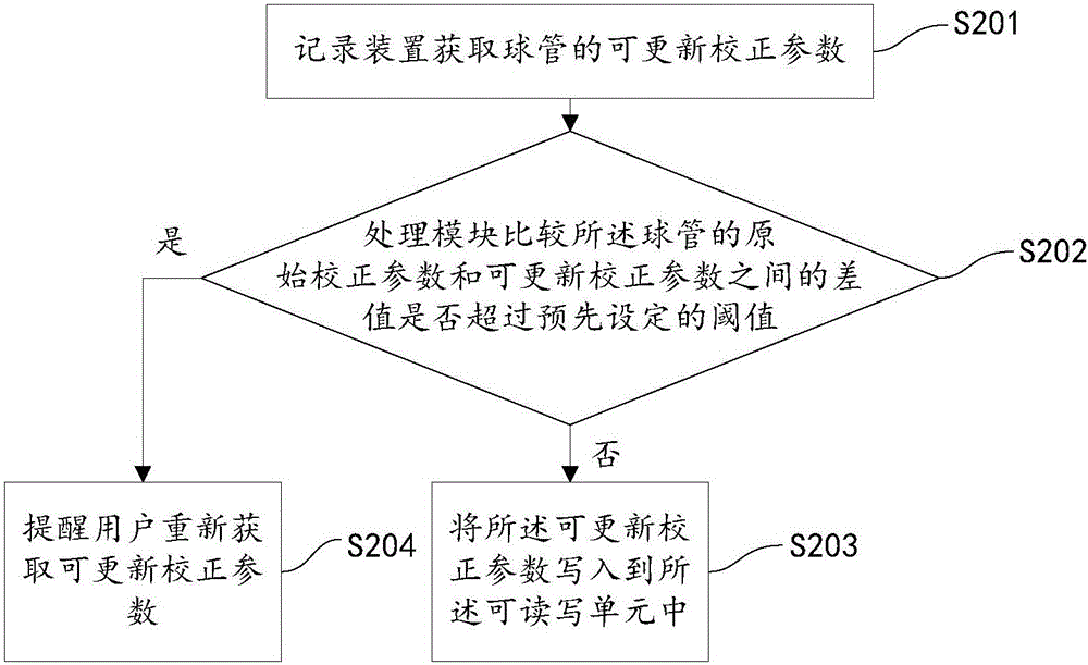
[0071] The present invention also proposes a working method of the ball tube with the above-mentioned recording device, figure 2 It is a flow chart of the bulb working method of an embodiment of the present invention, as figure 2 As shown, the method includes the following steps:

[0072] Step S201 is executed, and the recording device 100 acquires updateable correction parameters of the tube.

[0073] The original correction parameters and the updateable correction parameters in the present invention refer to the correction parameters related to the tube, and the updateable correction parameters may include but not limited to: the grid shown in Table 2 Voltage correction table or bulb filament correction table as shown in Table 3, etc.

[0074] Usually, a set of calibration procedures will be executed to obtain the updateable calibration parameters of the tube. The method for obtaining the updateable calibration parameters of the tube may be to obtain the updateable calib...

Embodiment 2

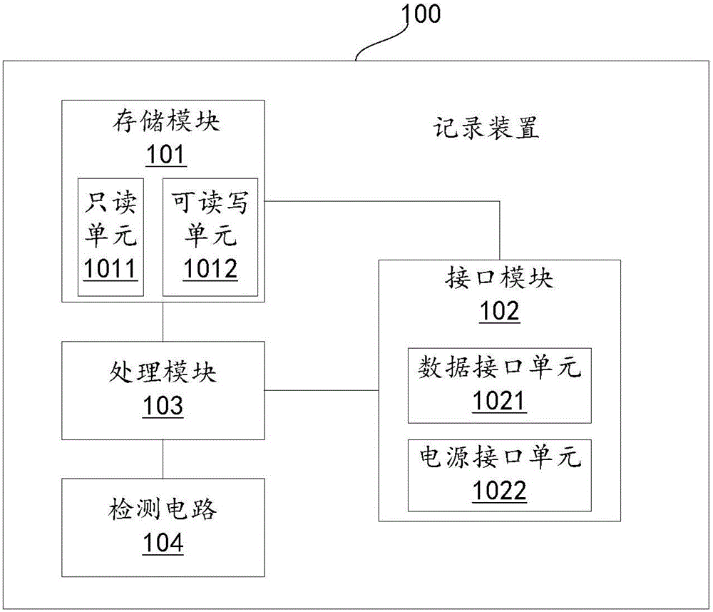
[0081] On the basis of the first embodiment, the readable and writable unit 1012 of the storage module 101 of the recording device 100 of this embodiment can also be used to store the historical usage information of the ball tube.

[0082] The historical use information includes, but is not limited to, the cumulative exposure seconds of the tube, the cumulative scanning energy of the tube, the number of rotations of the anode target of the tube, or the cumulative filament current energy of the tube.

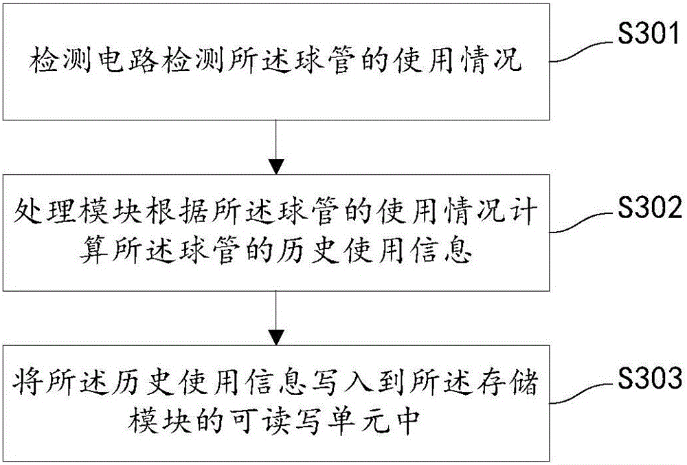
[0083] The detection circuit 104 can also be used to detect the use of the tube when the tube is in use, including but not limited to, the tube voltage of the tube, the tube current of the tube, the current circuit of the tube filament or the rotational speed of the anode of the tube .

[0084] The processing module 103 may also be configured to calculate historical usage information of the tube according to the usage of the tube.

[0085] image 3 It is a flow chart of the bul...


PUM


Abstract

The invention provides a bulb tube. The bulb tube comprises at least one recording apparatus, wherein the recording apparatus comprises a storage module and an interface module; the storage module is used for storing at least one kind of the basic information, the correction information and the historical use information of the bulb tube; the interface module is connected with the storage module; the interface module comprises a data interface unit and a power supply interface unit; and the data interface unit is used for realizing transmission between the recording apparatus and external data. The bulb tube provided by the invention is equipped with the recording apparatus, so that the related information of the bulb tube can be stored without manually inputting the related information; in addition, the information can be still kept and read directly when the bulb tube is replaced; the information can be used for correction or failure analysis and monitoring on the bulb tube; the management and replacement process of the bulb tube can be simplified; and convenience is brought to the maintenance of the bulb tube, and the user experience is improved. In addition, the invention also provides an operating method for the bulb tube.

Description

【Technical field】 [0001] The invention relates to the technical field of medical imaging, in particular to a ball tube and a working method thereof. 【Background technique】 [0002] The bulb is used to generate X-rays, also known as X-ray source. The X-ray tube includes a sleeve, a tube core and a heat dissipation part, wherein the tube core is composed of a cathode filament, an anode target, and a cermet or glass tube core shell. The high-voltage generator is used to heat the filament, and the high-voltage output end of the high-voltage generator They are respectively clamped at both ends of the cathode filament and the anode target, providing a high-voltage electric field to accelerate the active electrons on the filament to flow to the anode target, forming a high-speed electron flow. After bombarding the anode target surface, X-rays are generated due to the Compton effect. [0003] The tube is an important part of the X-ray imaging system. The basic information of the e...

Claims


Application Information

Patent Timeline
Patent Type & Authority Applications(China)
IPC IPC(8): H01J35/02
CPCH01J35/025
Inventor 何涛周家稳范洲远
Owner SHANGHAI UNITED IMAGING HEALTHCARE
Why Eureka
Try Eureka