A method to introduce solid impurities to the silicon material in the room temperature environment

A silicon material, solid-state technology, applied in semiconductor/solid-state device manufacturing, electrical components, circuits, etc., can solve problems such as polluting the environment, high cost, and contamination of silicon materials

Active Publication Date: 2019-05-14
BEIJING NAURA MICROELECTRONICS EQUIP CO LTD
View PDF5 Cites 0 Cited by
  • Summary
  • Abstract
  • Description
  • Claims
  • Application Information

AI Technical Summary

Problems solved by technology

Thermal diffusion usually requires a high temperature of seven, eight hundred or even thousands of degrees Celsius and a long time. Not only is the procedure complicated, the cost is high, the energy consumption is huge, and the environment is polluted, but also the silicon material is easily contaminated by impurities from the surrounding environment during the high-temperature heating process.
Ion implantation equipment is very expensive and difficult to be widely used in industrial production; moreover, ion implantation will generate a large number of defects in silicon materials, after ion implantation, high temperature annealing must be performed to eliminate these defects
However, some of these defects cannot be completely eliminated even after high-temperature annealing, which affects the performance of silicon materials.

Method used


Image

  • A method to introduce solid impurities to the silicon material in the room temperature environment
  • A method to introduce solid impurities to the silicon material in the room temperature environment

Examples


Embodiment 1

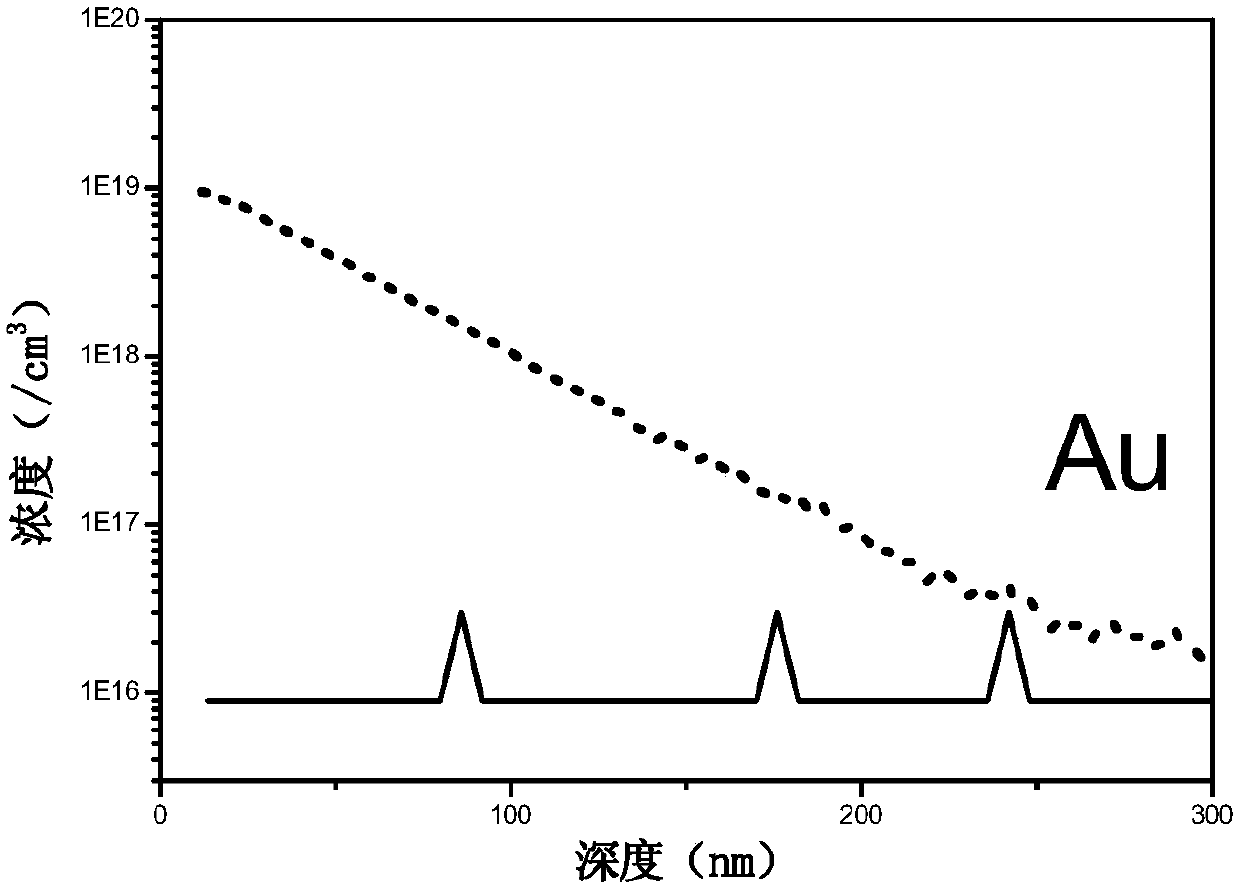
[0026] A P-type solar-grade Czochralski silicon single wafer is selected, polished on one side, with a resistivity of 1.9Ω·cm and a thickness of 625μm. Firstly, silicon wafers were ultrasonically cleaned with acetone, ethanol, and deionized water for 10 min, and then immersed in 2% HF solution to remove the natural oxide layer on the surface of the silicon wafers. Then the gold foil is placed in the center of the bottom of the plasma reaction chamber, the silicon wafer faces the gold foil, and is placed in an area at a certain distance from the center of the bottom of the plasma reaction chamber. The working gas is helium, the flow rate is 22sccm, and the vacuum degree is about 5E-3Pa. The power of the excitation power supply is 750W, and the processing time is 2min. Finally, the SIMS method was used to obtain the distribution of Au impurity concentration with depth in the sample after plasma treatment. The results are as follows: figure 1 shown. After 750W plasma treatment...

Embodiment 2

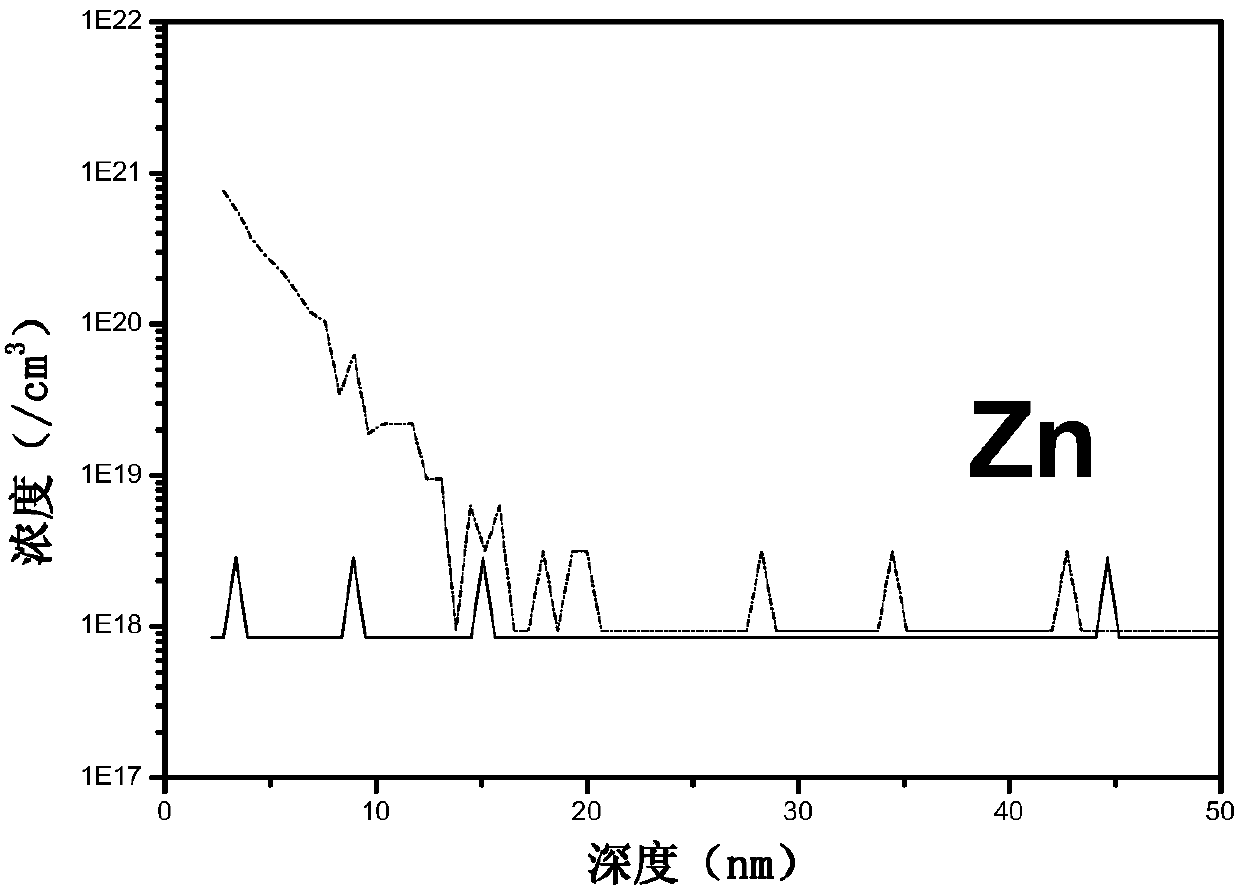
[0028] A P-type solar-grade Czochralski silicon single wafer is selected, polished on one side, with a resistivity of 1.9Ω·cm and a thickness of 625μm. Firstly, silicon wafers were ultrasonically cleaned with acetone, ethanol, and deionized water for 10 min, and then immersed in 2% HF solution to remove the natural oxide layer on the surface of the silicon wafers. Next, the zinc ingot is placed in the center of the bottom of the plasma reaction chamber, and the silicon sheet faces the zinc ingot, and is placed in an area at a certain distance from the center of the bottom of the plasma reaction chamber. The working gas is helium, the flow rate is 22sccm, and the vacuum degree is about 5E-3Pa. The power of the excitation power supply is 750W, and the processing time is 2min. Finally, the SIMS method was used to obtain the distribution of Zn impurity concentration with depth in the sample after plasma treatment. The results are as follows: figure 2 shown. After 750W plasma t...


PUM


Abstract

The invention discloses a method for introducing solid impurities into a silicon material under a room temperature environment. A solid impurity source is processed by using plasmas generated by inert gas under the room temperature environment, so that atoms or ions in the solid impurity source enter into the plasmas, the atoms or ions acquire kinetic energy through collision of positive ions and electrons in the plasmas, and then the atoms or ions enter into the silicon material. According to the method, due to the fact that high temperature is not needed, the method can be used for doping silicon wafers and can also be used for doping silicon devices, and compared with a traditional impurity introduction manner, the method is convenient and economical.

Description

technical field [0001] The invention relates to the technical field of semiconductors, in particular to a method for introducing solid impurities into silicon materials under room temperature conditions. Background technique [0002] Impurities in silicon have a very important impact on the properties of silicon. It can be said that silicon has little application without impurities. The introduction of impurities into silicon materials is of great significance in the semiconductor industry. Introducing impurities such as phosphorus and arsenic into high-purity silicon can obtain n-type silicon, while introducing impurities such as boron into high-purity silicon can obtain p-type silicon. The introduction of acceptor impurities on the surface of n-type silicon, or the introduction of donor impurities on the surface of p-type silicon, can obtain silicon p-n junctions, which are the basis of many silicon devices. In addition, if the transition metal impurity gold or platinum i...

Claims


Application Information

Patent Timeline
Patent Type & Authority Patents(China)
IPC IPC(8): H01L21/265
CPCH01L21/26513
Inventor 秦国刚侯瑞祥李磊徐万劲
Owner BEIJING NAURA MICROELECTRONICS EQUIP CO LTD
Why Eureka
Try Eureka