Cam clamping mechanism

A cam clamping and cam technology, applied in workpiece clamping devices, circuit board tool positioning, electrical components, etc., can solve the problems of cumbersome control and complex structure of the clamping and positioning mechanism, and achieve low cost, simple and fast mechanism structure The effect of clamping positioning

Active Publication Date: 2016-11-09
BOZHON PRECISION IND TECH CO LTD
View PDF5 Cites 12 Cited by
  • Summary
  • Abstract
  • Description
  • Claims
  • Application Information

AI Technical Summary

Problems solved by technology

[0003] The technical problem solved by the present invention: the control of the clamping and positioning mechanism in the prior art is cumbersome and the structure is complex

Method used


Image

  • Cam clamping mechanism
  • Cam clamping mechanism
  • Cam clamping mechanism

Examples


Embodiment Construction

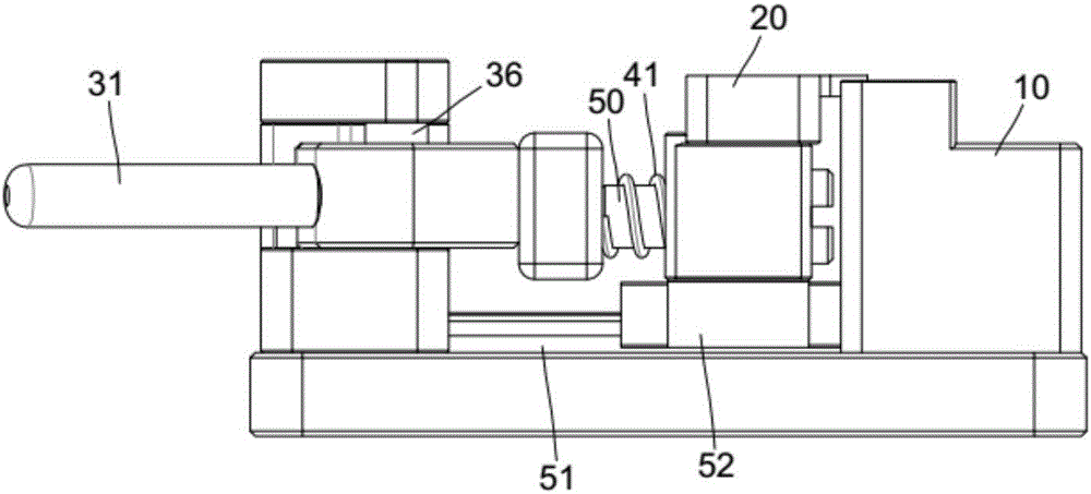
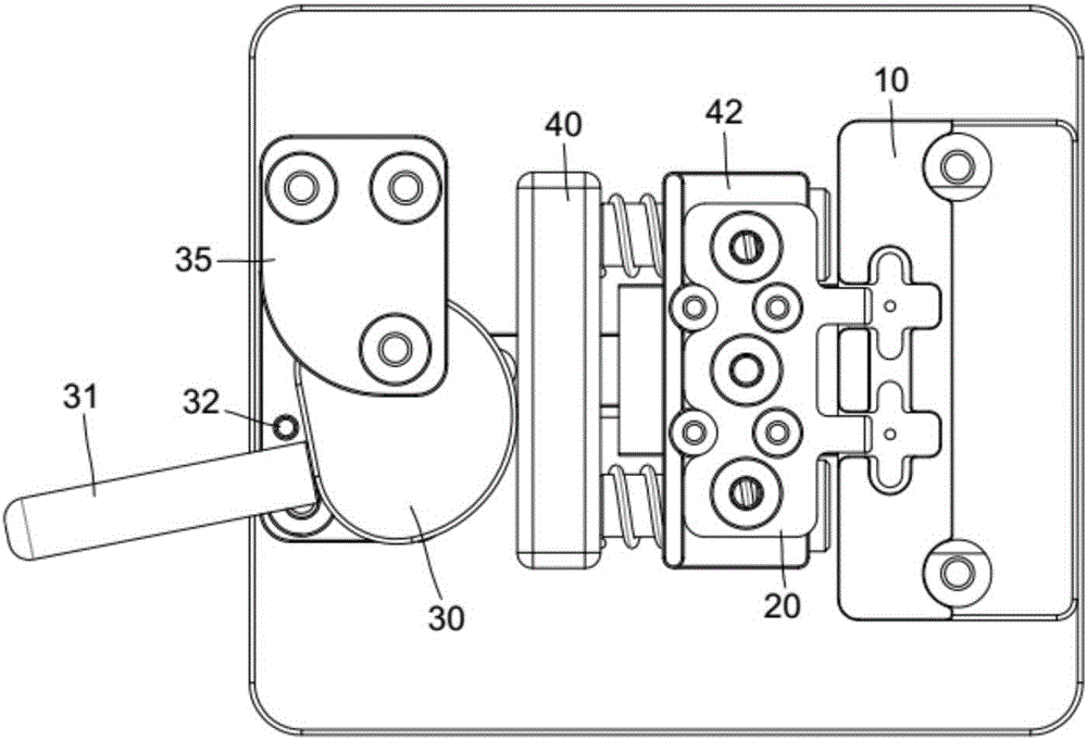
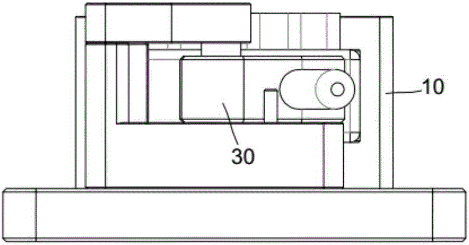
[0026] refer to Figure 4 , a cam clamping mechanism, including a clamping block 20 located on the side of the carrier 10, a guide mechanism for guiding the linear movement of the clamping block, and the clamping block is driven by a cam 30.

[0027] combine figure 2 , Figure 4 , the cam 30 is rotatably mounted on the camshaft 36 . The clamping base plate 60 is fixedly equipped with a cam base 34, and the cam base is fixedly locked with a cam shaft fixed block 35 through a tooth hole, and the cam shaft 36 is installed between the cam shaft fixed block and the cam base. The cam is fixed with a cam lever 31, which is used in conjunction with a stop post 32 on the cam base to block and limit the cam lever.

[0028] combine figure 1 , figure 2 , Figure 4 , the cam 30 drives the clamping block 20 through the elastic assembly. The elastic assembly includes a forward push block 40 in contact with the cam 30 , and a fixed block 42 connected to the forward push block through...


PUM


Abstract

The invention relates to a cam clamping mechanism. The cam clamping mechanism includes a clamping block arranged beside a carrier, and a guide mechanism for guiding the linear motion of the clamping block; the clamping block is driven by a cam; and elastic pieces are arranged between the cam and the clamping block. In operation, the cam rotates and drives the clamping block to move linearly along the guide mechanism, so that the clamping block pushes a product in the carrier so as to clamp and position the product. The cam clamping mechanism of the invention has the advantages of simple structure and low cost. With the elastic pieces adopted, damage to the product during a clamping process can be effectively avoided. Clamping and positioning are quick, so that the improvement of production efficiency can be benefitted.

Description

technical field [0001] The invention relates to the technical field of electronic product production, in particular to a clamping mechanism for electronic products. Background technique [0002] During the processing or assembly of the PCB board, the PCB board needs to be clamped and positioned. In the prior art, the cylinder is generally used as the power device for clamping and positioning. The air pressure control of the cylinder is cumbersome. complex structure. Contents of the invention [0003] The technical problem solved by the present invention: the control of the clamping and positioning mechanism in the prior art is complicated and the structure is complicated. [0004] In order to solve the above-mentioned technical problems, the present invention provides the following technical solutions: a cam clamping mechanism, including a clamping block located on the side of the carrier, and a guide mechanism for guiding the linear movement of the clamping block, the cl...

Claims


Application Information

Patent Timeline
Patent Type & Authority Applications(China)
IPC IPC(8): H05K3/00B25B11/02
CPCB25B11/02H05K3/0008
Inventor 吕绍林杨愉强王建福张杰
Owner BOZHON PRECISION IND TECH CO LTD
Why Eureka
Try Eureka