Anti-blocking aquarium water discharging pipe
A technology for aquariums and drain pipes, applied in fish farming, application, animal husbandry, etc., can solve the problems of power consumption, blockage of drain pipes, and inability to completely drain stagnant water, etc., and achieves low cost, simple operation, and simple structure Effect
- Summary
- Abstract
- Description
- Claims
- Application Information
AI Technical Summary
Problems solved by technology
Method used
Image
Examples
Embodiment 1
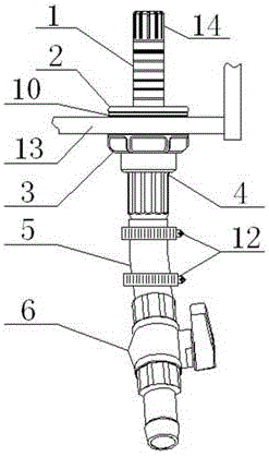
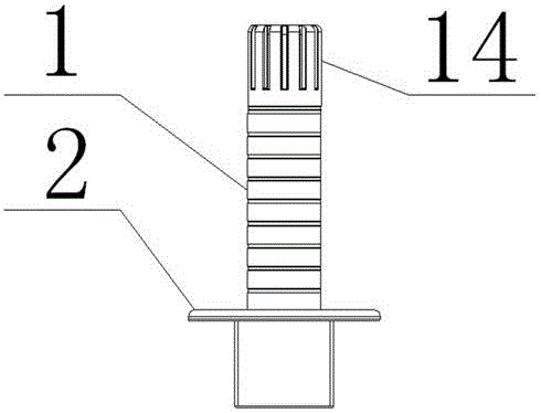
[0026] A clog-resistant aquarium drain such as figure 1 , figure 2 , Figure 4 As shown, it is specially set to the following structure: including the telescopic tube 1 arranged at the inner bottom of the aquarium 13 and the inner tooth flange 3 at the bottom of the outer side of the aquarium 13, the bottom of the telescopic tube 1 is connected with the outer tooth flange 2, and the outer tooth flange 2 is connected to the bottom of the telescopic tube 1. The free end of the flange 2 runs through the water outlet and connects with the inner flange 3, and the top of the telescopic tube 1 is provided with a plurality of water discharge holes 14 evenly distributed along its circumference; through the inner flange 3 and the outer flange 2 The threaded connection makes the telescopic tube 1 firmly fixed in the inside of the aquarium 13, and the water higher than the water discharge hole 14 will flow out of the aquarium 13 from the water discharge hole 14, and the width of the wat...
Embodiment 2
[0029] This embodiment is further optimized on the basis of the above-mentioned embodiments, further to better realize the present invention, such as figure 1 , figure 2 , Figure 4 As shown, the following arrangement structure is adopted in particular: the water discharge hole 14 is a rectangular through hole, and the long side of the water discharge hole 14 is arranged along the axial direction of the telescopic tube 1; Water enters at the same time at the same height, which improves the efficiency of water discharge, and makes the final water surface height after water discharge less than the height of the top of the telescopic tube 1 .
Embodiment 3
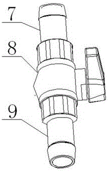
[0031] This embodiment is further optimized on the basis of the above-mentioned embodiments, further to better realize the present invention, such as figure 1 , image 3 , Figure 4 As shown, the following arrangement structure is particularly adopted: the free end of the outer tooth flange 2 is connected with a telescopic sleeve 4, the free end of the telescopic sleeve 4 is connected with an intermediate pipe 5, and the free end of the intermediate pipe 5 is connected with a ball valve assembly. 6; the ball valve assembly 6 includes the water inlet pipe 7 connected to the free end of the intermediate pipe 5, the ball valve 8 connected to the water inlet pipe 7 free end and the water outlet pipe 9 connected to the ball valve 8 free end; the ball valve assembly 6 can Control the on-off of the drain pipe, and then close the ball valve assembly 6 when it is necessary to stop draining halfway.
PUM
 Abstract
Description
Claims
Application Information
 - R&D Engineer
- R&D Manager
- IP Professional
- Industry Leading Data Capabilities
- Powerful AI technology
- Patent DNA Extraction
Browse by: Latest US Patents, China's latest patents, Technical Efficacy Thesaurus, Application Domain, Technology Topic, Popular Technical Reports.
© 2024 PatSnap. All rights reserved.Legal|Privacy policy|Modern Slavery Act Transparency Statement|Sitemap|About US| Contact US: help@patsnap.com


