Navigation positioning device and method for transcranial magnetic stimulator

A transcranial magnetic stimulation, navigation and positioning technology, applied in the field of medical assistance, can solve the problems of no real-time display of induced electric field distribution, limit the use of optical positioning systems, increase stimulation intensity, etc., achieve intuitive and convenient operation, solve automatic navigation and repetitive Targeting, addressing the effects of precise targeting and repeated targeting

Inactive Publication Date: 2016-11-16
沈阳爱锐宝科技有限公司
View PDF10 Cites 35 Cited by
  • Summary
  • Abstract
  • Description
  • Claims
  • Application Information

AI Technical Summary

Problems solved by technology

The machine vision positioning and navigation system requires a positioning cap. The thickness of the positioning cap increases the distance between the coil and the cerebral cortex, increases the stimulation intensity, and causes a waste of energy, especially when transcranial magnetic stimulation and EEG recording are required at the same time. Positioning caps and EEG electrode caps will increase the distance between the coil and the cerebral cor

Method used


Image

  • Navigation positioning device and method for transcranial magnetic stimulator
  • Navigation positioning device and method for transcranial magnetic stimulator
  • Navigation positioning device and method for transcranial magnetic stimulator

Examples


Embodiment 1

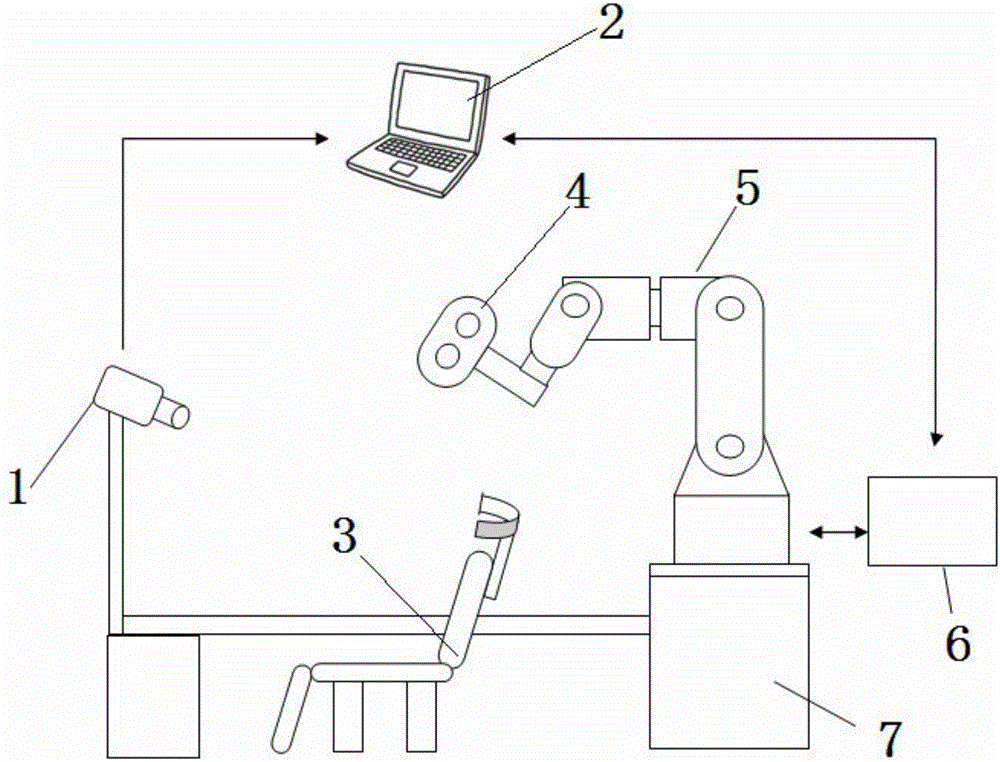
[0027] This embodiment provides a navigation and positioning device for a transcranial magnetic stimulator, which is characterized in that: the navigation and positioning device for a transcranial magnetic stimulator includes a visual positioning module 1, a computer 2, a seat 3, a transcranial magnetic Stimulator coil 4, robotic arm 5, robotic arm controller 6, base 7;

[0028] Wherein: the visual positioning module 1 is connected with the computer 2, the seat 3 is positioned between the base 7 and the visual positioning module 1 through the slideway, the transcranial magnetic stimulator coil 4 is installed on the front end of the mechanical arm 5, and the mechanical arm 5 is installed on the base On the seat 7, the mechanical arm 5 is connected with the mechanical arm controller 6; the mechanical arm controller 6 is connected with the computer 2.

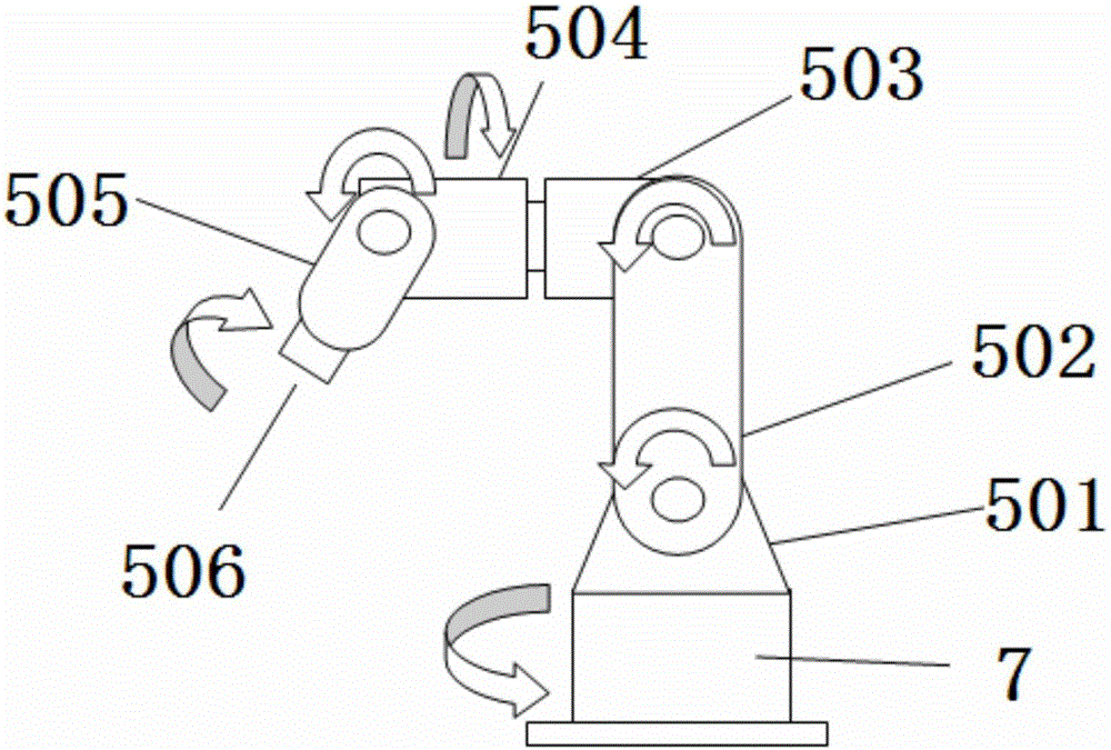
[0029] The mechanical arm 5 includes an I axis 501, an I axis 501, an II axis 502, a III axis 503, an IV axis 504, a V axis 505,...

Embodiment 2

[0043] This embodiment provides a navigation and positioning device for a transcranial magnetic stimulator, which is characterized in that: the navigation and positioning device for a transcranial magnetic stimulator includes a visual positioning module 1, a computer 2, a seat 3, a transcranial magnetic Stimulator coil 4, robotic arm 5, robotic arm controller 6, base 7;

[0044] Wherein: the visual positioning module 1 is connected with the computer 2, the seat 3 is positioned between the base 7 and the visual positioning module 1 through the slideway, the transcranial magnetic stimulator coil 4 is installed on the front end of the mechanical arm 5, and the mechanical arm 5 is installed on the base On the seat 7, the mechanical arm 5 is connected with the mechanical arm controller 6; the mechanical arm controller 6 is connected with the computer 2.

[0045] The mechanical arm 5 includes an I axis 501, an I axis 501, an II axis 502, a III axis 503, an IV axis 504, a V axis 505,...

Embodiment 3

[0058] This embodiment provides a navigation and positioning device for a transcranial magnetic stimulator, which is characterized in that: the navigation and positioning device for a transcranial magnetic stimulator includes a visual positioning module 1, a computer 2, a seat 3, a transcranial magnetic Stimulator coil 4, robotic arm 5, robotic arm controller 6, base 7;

[0059] Wherein: the visual positioning module 1 is connected with the computer 2, the seat 3 is positioned between the base 7 and the visual positioning module 1 through the slideway, the transcranial magnetic stimulator coil 4 is installed on the front end of the mechanical arm 5, and the mechanical arm 5 is installed on the base On the seat 7, the mechanical arm 5 is connected with the mechanical arm controller 6; the mechanical arm controller 6 is connected with the computer 2.

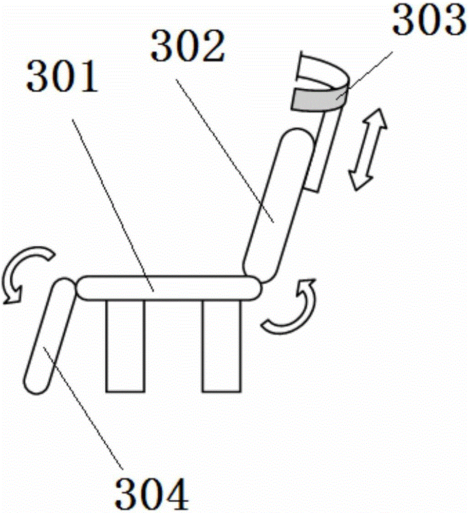
[0060] The seat 3 includes a load-bearing part 301, a backrest 302, a head rest 303, and a leg rest 304; wherein: the bottom loa...


PUM


Abstract

The invention discloses a navigation positioning device for a transcranial magnetic stimulator, and the device comprises a visual positioning module, a computer, a seat, a transcranial magnetic stimulator coil, a mechanical arm, a mechanical arm controller, and a base. The visual positioning module is connected with the computer, and the positioning between the seat and the base and visual positioning module is carried out through a slideway. The transcranial magnetic stimulator coil is disposed at the front end of the mechanical arm, and the mechanical arm is disposed on the base. The mechanical arm is connected with the mechanical arm controller. The mechanical arm controller is connected with the computer. The invention also discloses a positioning method for the device, and the method comprises the steps: building a head model; collecting and processing an image; calculating the coordinates of a target spot; carrying out the coil positioning; carrying out the repeated positioning; carrying out the stimulation treatment; and enabling the coil to return to a standby position after stimulation. The device is characterized in that the device directly detect a human face through employing machine vision, carries out positioning, is high in instantaneity, and enables a patient not to need to wear an auxiliary tool on the head; the device is quick in positioning, is high in repetition precision, and reduces the positioning time and workload; and the device can automatically track the target spot, and guarantees the effectiveness of treatment.

Description

technical field [0001] The invention relates to the field of medical assistance, in particular to a navigation and positioning device and a positioning method for a transcranial magnetic stimulator. Background technique [0002] In the early 1980s, British scientists Baker and others began to study the use of magnetic stimulation to intervene in brain neural activity, and successfully stimulated the motor center of the human brain for the first time in 1985, and measured the motor cortical evoked potential (Motor- evoked potentials, MEPs). This also marks the entry of Transcranial Magnetic Stimulation (TMS) into the stage of history. With the development of high-power devices and the improvement of circuits, repetitive magnetic stimulators (Repetitive Transcranial Magnetic Stimulation, rTMS) appeared in the late 1980s, which can generate 1–100 pulses per second. According to the principle of electromagnetic induction, the magnetic stimulator releases the energy stored in t...

Claims


Application Information

Patent Timeline
IPC IPC(8): A61N2/04
CPCA61N2/006A61N2/02
Inventor 王波张志强庄坤于冰
Owner 沈阳爱锐宝科技有限公司
Why Eureka
Try Eureka