A multifunctional catenary operation trolley and its operation method

A workbench and catenary technology, applied in the direction of transporting passenger cars, track contact elements, railway car body parts, etc., can solve the problems of inflexible operation, high maintenance cost, incomplete functions, etc., and achieve increased working range and easy operation. , full-featured effects

Active Publication Date: 2018-06-22
ZHUZHOU XUYANG ELECTRICAL & MECHANICAL TECH DEV CO LTD
View PDF11 Cites 0 Cited by
  • Summary
  • Abstract
  • Description
  • Claims
  • Application Information

AI Technical Summary

Problems solved by technology

[0008] The catenary operation equipment in the above-mentioned patent documents all have problems such as incomplete functions, high cost of single purchase and maintenance, and inflexible operation.

Method used


Image

  • A multifunctional catenary operation trolley and its operation method
  • A multifunctional catenary operation trolley and its operation method
  • A multifunctional catenary operation trolley and its operation method

Examples


Embodiment 1

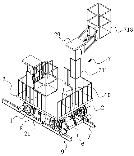
[0050] Embodiment 1: as Figure 1 to Figure 3 As shown, a multifunctional catenary operation trolley includes a front axle 1, a rear axle 2 and a working platform 3, and the front axle 1 and the rear axle 2 are connected together by an underframe 4, and the underframe 4 and located on the side of the front axle 1 is provided with a guide wheel support mechanism 1, on the underframe 4 and located on the side of the rear axle 2 is provided with a guide wheel support mechanism 2 6, the working platform 3 and the underframe 4 They are connected together by a leveling mechanism. The leveling mechanism is used to adjust the levelness of the working platform 3 during operation or walking. The telescopic rotating operating arm 7 is also arranged on the working platform 3, and the bottom frame 4 is provided with a preventive Anti-overturning mechanism for overturning during operation or walking. A hydraulic power system (not shown in the figure) is also provided on the underframe 4, a...

Embodiment 2

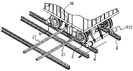
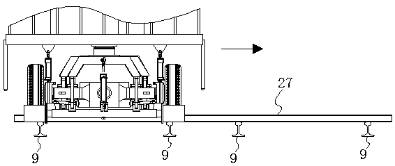
[0084] Embodiment 2: as Figure 12 and Figure 13 As shown, compared with Embodiment 1, the difference is that the anti-overturning device is a roller mechanism 28, and the roller mechanism 28 includes a left roller 281, a right roller 282, and an L-shaped connecting rod 283 hinged on the chassis 4. , the L-type connecting rod two 284 and the roller mechanism oil cylinder 285 hinged on the underframe 4; the left roller 281 is rotatably connected to one end of the L-type connecting rod 283, and the right roller 282 is rotatably connected to one end of the L-type connecting rod 284 On, one end of the roller mechanism oil cylinder 285 is hinged with the other end of the L-shaped connecting rod 283, and the other end of the roller mechanism oil cylinder 285 is hinged with the other end of the L-shaped connecting rod 284; the left roller 281 and the right roller 282 are located on two The position between the steel rails 9 and the left roller 281 is in contact with the side of a s...


PUM


Abstract

The invention discloses a multifunctional operation trolley for a contact line and an operation method thereof, wherein the multifunctional operation trolley for the contact line comprises a front axle, a back axle and a working platform, wherein the front axle is connected together with the back axle through a chassis; a guide wheel supporting mechanism I is arranged on the chassis and further at a position located on one side of the front axle; a guide wheel supporting mechanism II is arranged on the chassis and further at a position located on one side of the back axle; the working platform is connected together with the chassis through a leveling mechanism; the leveling mechanism is used for adjusting the levelness of the working platform during operation or walking; telescopic rotary operation arms are also arranged on the working platform; and an overturn preventing mechanism for preventing generating an overturn during the operation or the working is arranged on the chassis. The multifunctional operation trolley for the contact line is complete in functions, simple in structure, simple and convenient to operate and low in procurement cost and maintenance cost.

Description

technical field [0001] The invention relates to a maintenance equipment for catenary and its operation method, in particular to a multifunctional catenary operation trolley and its operation method. Background technique [0002] The catenary is a high-voltage transmission line erected along the zigzag above the rails in the electrified railway for the pantograph to take current. The distance between the contact wire and the locomotive pantograph is generally between 5700mm and 6500mm from the rail surface. The catenary is the main frame of the railway electrification project. It is a special form of transmission line erected along the railway line to supply power to the electric locomotive. It is composed of contact suspension, support device, positioning device, pillar and foundation. With the rapid development of China's railway transportation, the mileage of electrified railways and high-speed passenger dedicated lines has greatly increased, and the workload of catenary m...

Claims


Application Information

Patent Timeline
Patent Type & Authority Patents(China)
IPC IPC(8): B61D15/00B61F11/00B66F11/04B61K5/02
CPCB61D15/00B61F11/00B61K5/02B66F11/04
Inventor 邓建华杨永州吴俊雯尤旺
Owner ZHUZHOU XUYANG ELECTRICAL & MECHANICAL TECH DEV CO LTD
Why Eureka
Try Eureka