Microgravity simulation tension control mechanism with function of capable of adjusting load in a large range

A tension control mechanism, microgravity simulation technology, applied in the simulation device of space navigation conditions, space navigation equipment, transportation and packaging, etc., can solve the problems of weak damping characteristics, unadjustable load weight and so on

Active Publication Date: 2016-11-16
HARBIN INST OF TECH
View PDF8 Cites 6 Cited by
  • Summary
  • Abstract
  • Description
  • Claims
  • Application Information

AI Technical Summary

Problems solved by technology

[0006] The present invention provides a microgravity simulated tension control mechanism with a wide range of load adjustable function in order to solve th

Method used


Image

  • Microgravity simulation tension control mechanism with function of capable of adjusting load in a large range
  • Microgravity simulation tension control mechanism with function of capable of adjusting load in a large range
  • Microgravity simulation tension control mechanism with function of capable of adjusting load in a large range

Examples


specific Embodiment approach 1

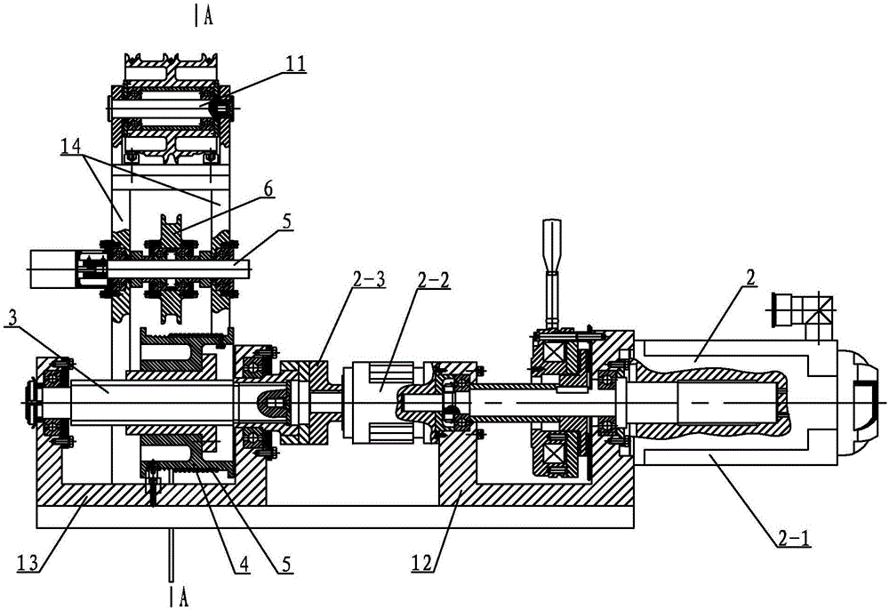
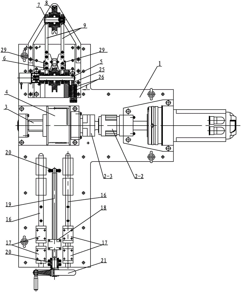
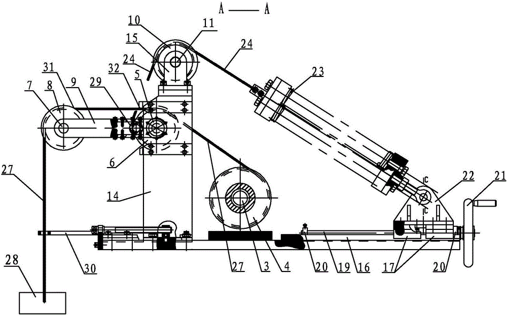
[0023] Specific implementation mode one: combine Figure 1 to Figure 9 Describe this embodiment, this embodiment includes base 1, driving part 2, driving shaft 3, winding wheel 4, driven shaft 5, swing arm bottom wheel 6, balance wheel shaft 7, balance wheel 8, swing lever 9, rope wheel 10 , guide wheel shaft 11, right support 12, left support 13, lower support 14, upper support 15, nut 18, screw 19, bearing seat 20, hand wheel 21, spring base 22, spring device 23, steel wire rope 24 , damping aluminum plate 25, sling 27, workpiece 28, two magnets 26, steel wire fixed wheel 29, two guide rails 16 and four sliders 17, the drive part 2 is installed on the right support 12, and the drive shaft 3 is installed on the left On the support 13, the right support 12 and the left support 13 are all fixed on the base 1, the input end of the drive shaft 3 is connected with the output shaft of the drive part 2, and the winding wheel 4 is fixed on the drive shaft 3, and the passive The shaf...

specific Embodiment approach 2

[0025] Specific implementation mode two: combination Figure 10 The present embodiment will be described. In this embodiment, the orientations of the N poles on the two magnets 26 are aligned, and the orientations of the S poles on the two magnets 26 are aligned. This setting can generate a magnetic field between the two magnets, and then the damping aluminum plate 25 cuts the magnetic induction lines to generate eddy currents, thereby providing motion resistance, reducing motion energy, and playing the role of energy absorption and shock absorption. Other components and connections are the same as those in the first embodiment.

specific Embodiment approach 3

[0026] Specific implementation mode three: combination image 3 This embodiment will be described. In this embodiment, the axis of the guide wheel shaft 11 and the axis of the driving shaft 5 are in the same horizontal plane. Other components and connections are the same as those in the second embodiment.


PUM


Abstract

The invention relates to a microgravity simulation tension control mechanism with a function of capable of adjusting a load in a large range, and aims to solve the problems that the weight of the load of a conventional suspension cable type microgravity simulation tension control buffering mechanism cannot be adjusted and the conventional suspension cable type microgravity simulation tension control buffering mechanism has weak damping characteristics. A driving shaft drives a driving component; a reel is fixedly mounted on the driving shaft; a swinging arm bottom wheel is mounted on a driven shaft; a swinging wheel is mounted on a swinging wheel shaft; each front swinging rod is connected with a corresponding rear swinging rod through a connecting element; a rope wheel is fixedly mounted on an upper bracket; a damping aluminum plate is arranged between two magnets; two sliding blocks are in sliding connection to each guide rail; a nut is in threaded connection with a screw rod; the nut and the four sliding blocks are separately and fixedly connected with a spring base; one end of a spring device is hinged to the spring base, and the other end of the spring device is fixedly connected with a steel wire rope; the other end of the steel wire rope goes around the rope wheel to be fixedly connected to a steel wire fixing wheel; and one end of a suspension cable is wound on the reel, and the other end of the suspension cable goes around the swinging arm bottom wheel and the swinging wheel to be connected with a work piece. The microgravity simulation tension control mechanism disclosed by the invention is used for simulating the working condition and each technical indicator of a space mechanism in ground environment.

Description

technical field [0001] The invention relates to a space microgravity simulation mechanism, in particular to a sling-type microgravity simulation tension control mechanism with a large-range adjustable load function. Background technique [0002] In the field of aerospace technology, in order to ensure the effective operation of space agencies, it is necessary to develop a ground simulation system for the microgravity space environment in the ground environment, and then analyze the various functions, performance indicators, reliability, operating procedures, failure modes and countermeasures of space agencies. Measures and other problems that may be encountered during the entire life cycle of the equipment are tested as complete and efficient as possible. [0003] The working conditions and various technical indicators of space manipulators, planetary exploration vehicles and other devices need to be evaluated in the ground environment during the research and development pro...

Claims


Application Information

Patent Timeline
IPC IPC(8): B64G7/00
CPCB64G7/00
Inventor 班晓军卢鸿谦尹航王博黄显林
Owner HARBIN INST OF TECH
Why Eureka
Try Eureka