A Microgravity Simulated Tension Control Mechanism with Large Range Adjustable Load
A tension control mechanism and microgravity simulation technology, which can be applied to simulation devices of space navigation conditions, space navigation equipment, transportation and packaging, etc., and can solve problems such as non-adjustable load weight and weak damping characteristics.
- Summary
- Abstract
- Description
- Claims
- Application Information
AI Technical Summary
Problems solved by technology
Method used
Image
Examples
specific Embodiment approach 1
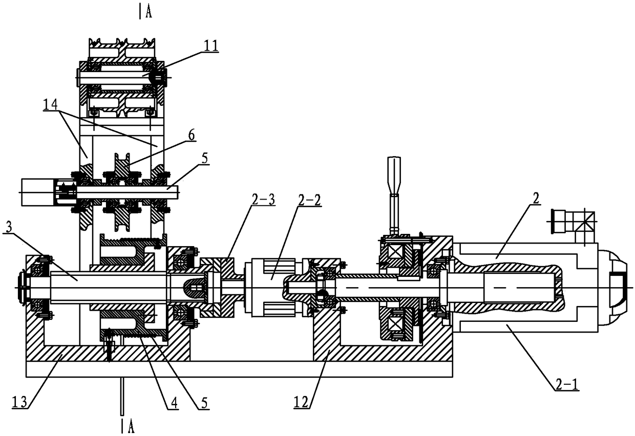
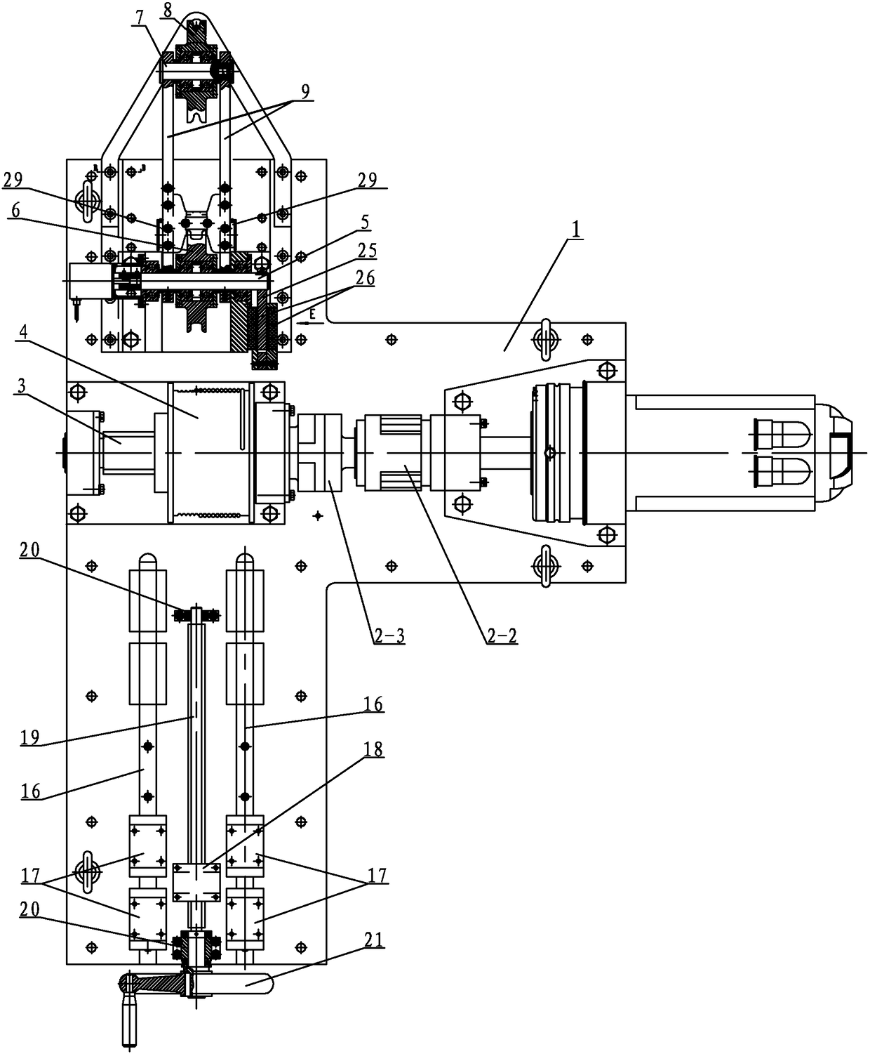
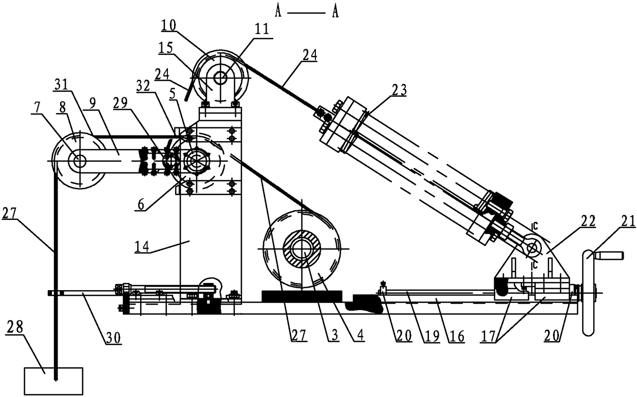
[0023] Specific implementation mode one: combine Figure 1 to Figure 9 Describe this embodiment, this embodiment includes base 1, driving part 2, driving shaft 3, winding wheel 4, driven shaft 5, swing arm bottom wheel 6, balance wheel shaft 7, balance wheel 8, swing lever 9, rope wheel 10 , guide wheel shaft 11, right support 12, left support 13, lower support 14, upper support 15, nut 18, screw 19, bearing seat 20, hand wheel 21, spring base 22, spring device 23, steel wire rope 24 , damping aluminum plate 25, sling 27, workpiece 28, two magnets 26, steel wire fixed wheel 29, two guide rails 16 and four sliders 17, the drive part 2 is installed on the right support 12, and the drive shaft 3 is installed on the left On the support 13, the right support 12 and the left support 13 are all fixed on the base 1, the input end of the drive shaft 3 is connected with the output shaft of the drive part 2, and the winding wheel 4 is fixed on the drive shaft 3, and the passive The shaf...
specific Embodiment approach 2
[0025] Specific implementation mode two: combination Figure 10 The present embodiment will be described. In this embodiment, the orientations of the N poles on the two magnets 26 are aligned, and the orientations of the S poles on the two magnets 26 are aligned. This setting can generate a magnetic field between the two magnets, and then the damping aluminum plate 25 cuts the magnetic induction lines to generate eddy currents, thereby providing motion resistance, reducing motion energy, and playing the role of energy absorption and shock absorption. Other components and connections are the same as those in the first embodiment.
specific Embodiment approach 3
[0026] Specific implementation mode three: combination image 3 This embodiment will be described. In this embodiment, the axis of the guide wheel shaft 11 and the axis of the driven shaft 5 are in the same horizontal plane. Other components and connections are the same as those in the second embodiment.
PUM
 Abstract
Description
Claims
Application Information
 - R&D
- Intellectual Property
- Life Sciences
- Materials
- Tech Scout
- Unparalleled Data Quality
- Higher Quality Content
- 60% Fewer Hallucinations
Browse by: Latest US Patents, China's latest patents, Technical Efficacy Thesaurus, Application Domain, Technology Topic, Popular Technical Reports.
© 2025 PatSnap. All rights reserved.Legal|Privacy policy|Modern Slavery Act Transparency Statement|Sitemap|About US| Contact US: help@patsnap.com


