
A New High Efficiency Cyclone

A cyclone and high-efficiency technology, which is applied in the field of new high-efficiency cyclones, can solve the problems of cyclone efficiency decline, difficult installation, and affecting separation efficiency, and achieve the effects of improving efficiency, convenient installation, and efficient use

Active Publication Date: 2019-11-15
QINGDAO ZHONGYA ENVIRONMENTAL ENG
View PDF5 Cites 0 Cited by
  • Summary
  • Abstract
  • Description
  • Claims
  • Application Information

AI Technical Summary

Problems solved by technology

[0003] The water inlet of the original cyclone is placed at the upper end of the cyclone, and the position is fixed. The installation is more restricted by the surrounding conditions, and the installation is not easy; The efficiency of the device decreases, which affects the separation efficiency

Method used


Image

  • A New High Efficiency Cyclone
  • A New High Efficiency Cyclone
  • A New High Efficiency Cyclone

Examples


Embodiment Construction

[0018] The present invention will be further described below in conjunction with the accompanying drawings and embodiments.

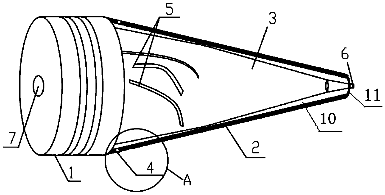
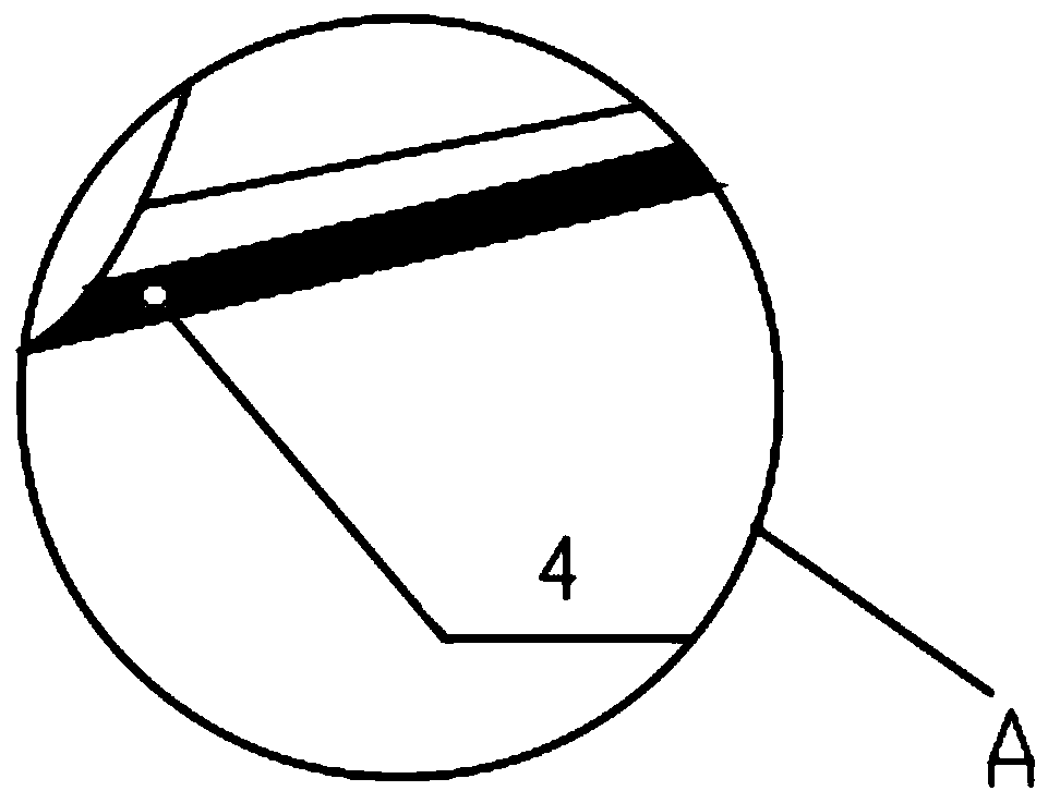
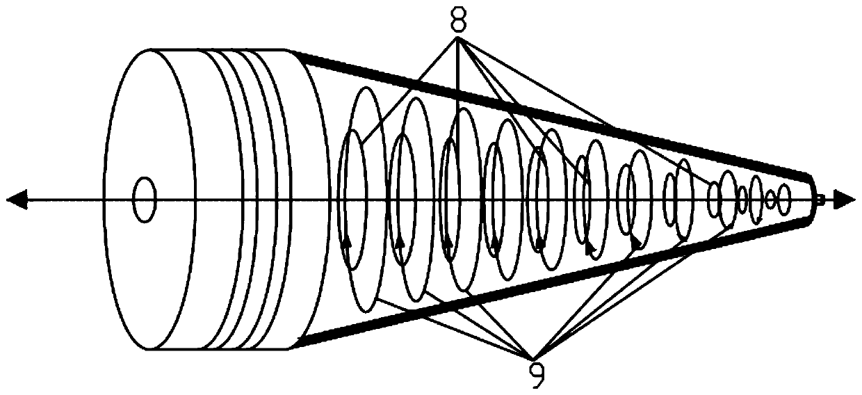
[0019] Such as Figure 1-3 As shown, a new high-efficiency cyclone includes a first shell 1, a second shell 2, and a swirl cavity 3 arranged in the first shell 1 and the second shell 2; wherein, the first shell The body 1 is a cylinder, the second shell 2 is a truncated cone, and the first shell 1 and the second shell 2 are connected to each other; the inner diameter of the second shell 2 starts from the connection with the first shell 1 along the gradually decreases along the axis, that is, the inner diameter of the second shell 2 in contact with the first shell 1 is larger than the inner diameter of the place away from the first shell 2; the swirl cavity 3 located in the second shell 2 corresponds to the second shell The truncated cone of the body 2 is also a truncated cone; correspondingly, the diameter of the cyclone cavity 3 near the first housing...


PUM


Abstract

The invention discloses a novel efficient swirler which comprises a first casing, a second casing, and a swirling cavity arranged in the first casing and the second casing; the first casing is a cylinder, the second casing is a truncated circular cone, the first casing and the second casing are mutually connected; an open pore is arranged at the tail part, far from one end of the first casing, of the second casing; the second casing is provided with a water inlet on the position close to the first casing; the swirling cavity is provided with a cavity water inflow trough on the position close to the first casing; the cavity water inflow trough corresponds to the water inlet internally and externally; a bottom flowing pore penetrating through the open pore at the tail part of the second casing is arranged in the axis center of the tail part, far from one end of the first casing, of the swirling cavity, and the swirling cavity is provided with an overflow port penetrating through the first casing in the axis center inside the first casing. By improving the water inflow structure and mode, the single water inlet is changed into two pores for water inflow, and with the match of the cavity water inflow trough, the problems of short flow and circulation flow in the swirling process are solved, and the swirling separation efficiency is greatly improved.

Description

technical field [0001] The invention relates to a cyclone, in particular to a novel high-efficiency cyclone. Background technique [0002] At present, the main methods of degreasing oily sewage are: gravity sedimentation method, physical chemical method, chemical coagulation method, coarse granulation method, filtration method, flotation method, activated carbon adsorption method, biological method, and electromagnetic method. Due to the difference in water quality and the depth of treatment required, it is difficult to achieve the expected purpose only by one degreasing method, so when used on site, several methods are used in combination. [0003] The water inlet of the original cyclone is placed at the upper end of the cyclone, and the position is fixed. The installation is more restricted by the surrounding conditions, and the installation is not easy; The efficiency of the device decreases, which affects the separation efficiency. Contents of the invention [0004] ...

Claims


Application Information

Patent Timeline
Patent Type & Authority Patents(China)
IPC IPC(8): C02F1/38C02F1/40B04C5/04
CPCB04C5/04C02F1/38C02F1/40
Inventor 苏效忠
Owner QINGDAO ZHONGYA ENVIRONMENTAL ENG
Learn More