Closed cooling system for soft water of blast furnace body and blast furnace cooling method

A soft water sealing and cooling system technology, applied in the direction of cooling devices, etc., can solve the problems of cooling intensity blast furnace thickening, low practicability, inability to achieve adjustment, etc., to prevent furnace wall thickening, prevent slag skin instability, and effectively adjust. Effect

Inactive Publication Date: 2016-11-16
武汉钢铁有限公司
View PDF4 Cites 9 Cited by
  • Summary
  • Abstract
  • Description
  • Claims
  • Application Information

AI Technical Summary

Problems solved by technology

These three water supply methods all have the same water flow in all channels in all cooling equipment in the zone and can only adjust the flow of the whole zone but cannot adjust the flow of different channels in the circumferential direction.
However, these three water supply methods have great limitations: that is, they cannot meet the cooling equipment's water requirements when the cooling equipment has a high heat load, and the excess water volume will cause waste of cooling water and excessive heat consumption during normal production hours. , the excess cooling intensity is also the main reason for accidents such as the thickness of the blast furnace and the occurrence of furnace tumors; at the same time, the temperature and slag skin conditions are different at different heights, different intervals during blast furnace production, and the required local cooling intensity requirements are also different.
However, the disadvantages of this system are: 1. The adjustment of the bypass flow of a certain flow channel will cause a small change in the water flow of the flow channel, and it will affect the flow of all stave channels in the same layer and different layers. 2. The inlet and outlet pipes of each flow channel are connected with a bypass pipe, which will form a dense "pipe cage" outside the furnace shell, so that the maintenance and maintenance of the furnace shell and stave water pipes Troubleshooting becomes extremely difficult and the technology is less useful
When it is intended to reduce the water volume of a stave flow channel, the bypass regulating valve of the flow channel should be opened larger, because all the water sources of the stave are supplied by the same ring pipe at the bottom, so even if the bypass is fully opened, the The flow rate of the water channel is only reduced by 1 / 201, that is, by about 0.5%. It can be seen that the maximum regulation capacity of the system is only 0.5%, which is far from achieving the purpose of regulation
Moreover, after the bypass regulating valve is enlarged, the water volume affecting the flow channels of the upper layer (section) and the lower layer (section) increases, and the flow of the other 199 water channels decreases accordingly, and even causes the disorder of the entire system
In addition, the distance between two adjacent bypass pipes in this system is 278mm, the outer diameter of the bypass pipe is at least 50mm, and the gap between the two pipes of the "tube cage" is only 228mm. When, it will be difficult for the operator to enter the furnace shell to work

Method used


Image

  • Closed cooling system for soft water of blast furnace body and blast furnace cooling method
  • Closed cooling system for soft water of blast furnace body and blast furnace cooling method
  • Closed cooling system for soft water of blast furnace body and blast furnace cooling method

Examples


Embodiment 1

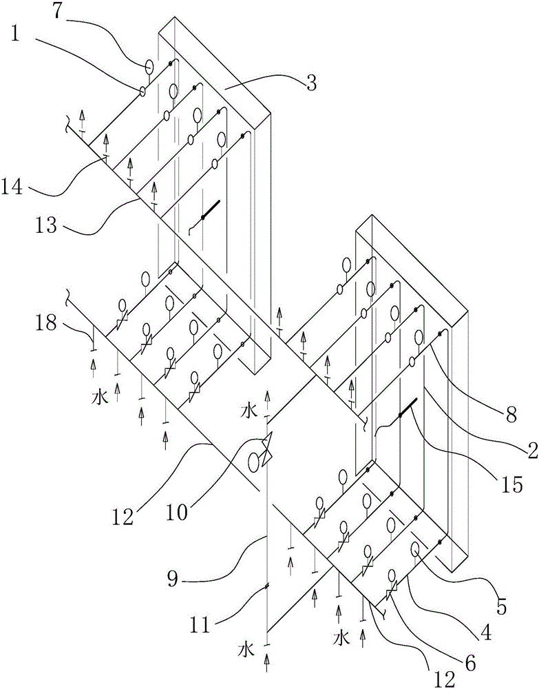
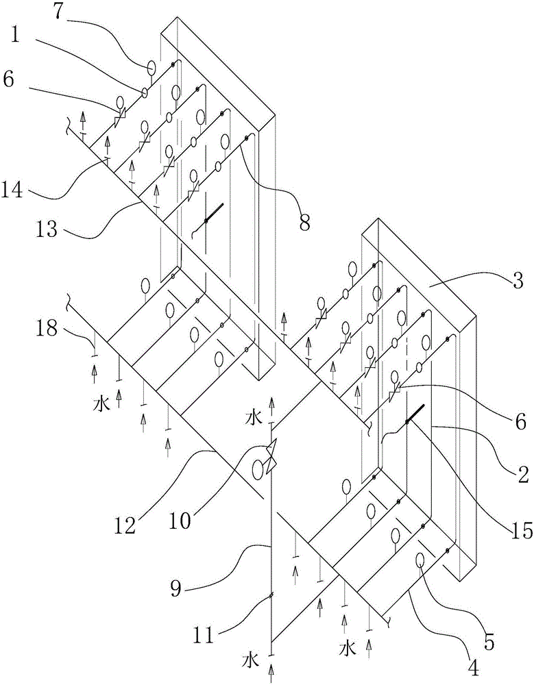
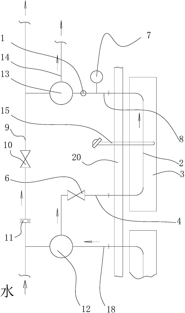
[0048] Such as figure 1 , image 3 As shown, a soft water closed cooling system for a blast furnace body includes a number of stave bodies 3 fixed to the inner wall of the blast furnace shell 20 with bolts. 48 cooling stave bodies are arranged in each layer, and each cooling stave body 3 is provided with four cooling water flow channels 2. Out of the blast furnace shell 20, and the first temperature sensor 5 and the second temperature sensor 7 are respectively installed on the water inlet pipe 4 and the water outlet pipe 8, the flow sensor 1 is arranged on the water inlet pipe 4 or the water outlet pipe 8, and the stave body 3 A third temperature measuring sensor 15 is installed on it, and the third temperature measuring sensor 15 penetrates the furnace shell 20 and goes deep into the stave body 3 . Every 6 stave bodies on the same floor are divided into 8 groups. The 24 water inlet pipes of each group of cooling wall bodies are connected with the water inlet concentration ...

Embodiment 2

[0055] The other structures of this embodiment are the same as those of Embodiment 1, the only difference being that all the water inlet pipes 4 of the stave body on the same floor are in communication with the water inlet concentration pipe 12, and the water inlet concentration pipe 12 is a ring pipe surrounding the blast furnace body. All the water outlet pipes 8 of the stave body on the same layer are connected with the water outlet centralized pipe 13, and the water outlet centralized pipe 13 is a ring pipe surrounding the blast furnace body. The outlet pipe 8 is provided with a first regulating valve 6, and the opening degree of the first regulating valve 6 is controlled to control the flow of water passing through the cooling wall as required, and at the same time, the opening of the second regulating valve 10 on the same group of bypass pipes 9 is changed. to avoid affecting the water flow in other parts of the flow channel.

[0056] The core of the present invention is...


PUM


Abstract

The invention discloses a closed cooling system for soft water of a blast furnace body and a blast furnace cooling method. The blast furnace cooling method comprises the steps that firstly, for cooling wall bodies on some layers of a blast furnace, water inlet pipes of the cooling wall bodies in the layer communicate with a water inlet centralizing pipe, and water outlet pipes of the cooling wall bodies in the layer communicate with a water outlet centralizing pipe; each water inlet pipe is provided with a first adjusting valve, one end of each bypass pipe communicates with the water inlet centralizing pipe, the other end of each bypass pipe communicates with the water outlet centralizing pipe, and the bypass valves are provided with second adjusting valves; secondly, the aperture of the first adjusting valves is controlled, flow of water in corresponding cooling water runners is increased or decreased so as to adjust the cooling strength of blast furnace areas corresponding to the cooling water runners, meanwhile, the reverse direction change of the aperture of the corresponding second adjusting valves is controlled, and therefore flow of water in other cooling water runners not needing adjustment is maintained not to be influenced. According to the closed cooling system, the system can be automatically controlled to adjust the passing cooling water amount according to the local heat load of the furnace body, and meanwhile it is guaranteed that adjustment in the area cannot influence flow in other areas.

Description

technical field [0001] The invention relates to a soft water closed cooling system for a blast furnace, in particular to a soft water closed cooling system for a blast furnace body and a blast furnace cooling method. Background technique [0002] The cooling equipment of the modern blast furnace body is mainly a stave installed on the inner wall of the furnace shell. The stave is divided into multiple layers (sections) along the height direction. There is at least one cooling water flow channel inside, and water flows through the flow channel to cool the wall during operation, which is used to maintain reasonable operation of the furnace type and protect the furnace shell and other structures. The structure of the large-scale blast furnace body cooling system has developed from the original old-fashioned industrial water open system to the current soft water closed cooling system. According to the cooling water distribution strategy, most of them adopt the bottom-up series c...

Claims


Application Information

Patent Timeline
Patent Type & Authority Applications(China)
IPC IPC(8): C21B7/10
CPCC21B7/10
Inventor 姜本熹
Owner 武汉钢铁有限公司
Why Eureka
Try Eureka