Composite splitter lip for axial turbomachine compressor

A turbomachinery and splitter technology, applied to the splitter lip of axial flow turbomachinery, manufacturing the field of splitter lip of axial flow turbomachinery, can solve problems such as stress concentration, reduce fuel consumption, optimize weight saving, The effect of reducing the number

Active Publication Date: 2016-11-16
SAFRAN AERO BOOSTERS SA
View PDF7 Cites 2 Cited by
  • Summary
  • Abstract
  • Description
  • Claims
  • Application Information

AI Technical Summary

Problems solved by technology

However, this method of mounting is weak due to the a

Method used


Image

  • Composite splitter lip for axial turbomachine compressor
  • Composite splitter lip for axial turbomachine compressor
  • Composite splitter lip for axial turbomachine compressor

Examples


Embodiment Construction

[0051] In the following description, the terms "inner" or "inner" and "outer" or "outer" refer to a position relative to the axis of the axial turbomachine. The axial direction corresponds to a direction along the rotational axis of the turbomachine.

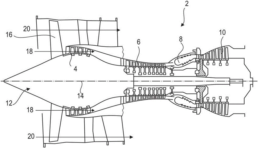
[0052] figure 1 is a simplified illustration of an axial turbomachine. In this particular case, it's a turbofan engine. Engine 2 includes a first compression stage known as low pressure compressor 4 and a second compression stage known as high pressure compressor 6 , a combustion chamber 8 and one or more turbine stages 10 . In operation, the two compressors 4 and 6 are driven by the mechanical power of the turbine 10 transmitted through the central shaft to the rotor 12 . These compressors 4 and 6 comprise rows of rotor blades associated with rows of stator vanes. The rotation of the rotor about its axis of rotation 14 makes it possible to generate and progressively compress the air flow to the inlet into the combustion cha...


PUM


Abstract

The invention proposes a splitter lip 22 for a low-pressure compressor of an axial turbomachine for an aeroplane. The splitter lip 22 comprises an upstream annular wall 36 made of metal with a circular leading edge 30, and a downstream annular partition 38 made of an organic-matrix, short-fibre composite material. The splitter lip also supports an outer shroud 28 for a stator upstream of the compressor. The upstream wall comprises an annular anchoring portion 40 arranged in the thickness of the downstream partition 38 so as to anchor the partition and the wall to one another. The anchoring portion 40 has distributed hexagonal openings in order to increase anchoring. The invention also proposes a method for producing, by moulding, a bi-material splitter lip or a mixed lip.

Description

technical field [0001] The invention relates to air inlets for axial flow turbomachines. More precisely, the present invention relates to splitter lips for axial flow turbomachines. The invention also contemplates a method for manufacturing a splitter lip of an axial turbomachine. Background technique [0002] To protect the environment, turbofan engines have been developed. In this case, protecting the environment is intended to severely limit noise and reduce consumption. In order to optimize thrust and performance while reducing noise, jet engines use multiple annular airflows, eg two or three. [0003] Typically, turbomachines split an incoming airflow into a primary airflow and a secondary airflow in the form of an annular sleeve. The primary airflow passes through the compressor, combustor and then expands in the turbine. The secondary airflow passes around the outside of the compressor, combustor and turbine and then rejoins the primary airflow at the exit of the...

Claims


Application Information

Patent Timeline
IPC IPC(8): F01D25/00
CPCF01D25/00F01D25/24F02C7/04F02C7/047F05D2230/60F05D2300/603Y02T50/60F02C3/04F04D19/02F04D29/023F04D29/522F04D29/701F05D2220/32
Inventor D.布永G.赫尔鲍特
Owner SAFRAN AERO BOOSTERS SA
Why Eureka
Try Eureka