
Solar heat collecting pipe and manufacturing method thereof

A technology for solar heat collecting tubes and manufacturing methods, which is applied in the directions of solar heat collectors, solar thermal energy, and solar thermal power generation, and can solve the problems of bursting of heat collecting tubes, poor resistance to rapid cooling and rapid heating, and poor resistance to rapid cooling and rapid heating of glass tubes, etc. , to achieve the effects of reducing the impact of the use environment, enhancing diffusion and refraction, and improving thermal insulation performance

Inactive Publication Date: 2016-11-16
芜湖市万里达新能源有限公司
View PDF9 Cites 0 Cited by
  • Summary
  • Abstract
  • Description
  • Claims
  • Application Information

AI Technical Summary

Problems solved by technology

[0002] Solar water heaters have been widely used in recent years because they use sunlight to obtain a steady stream of energy. However, many solar water heaters are affected by the environment in which they are used. In cloudy and rainy days or in winter with short sunshine hours, the solar heat collector tubes do not absorb enough heat, resulting in solar energy. The water heater cannot be used normally, and even due to the abnormal climate, the glass tube has poor resistance to rapid cooling and rapid heating, and the solar collector tube bursts. The existing technology solves the problem of low water temperature caused by insufficient sunlight by using electric energy compensation or other temperature compensation methods. , this compensation method, limited by the installation conditions, is difficult to use in an extremely cold environment. In order to avoid the phenomenon of bursting of the heat collection tube caused by the poor performance of the glass tube in rapid cooling and rapid heating, it is idle in winter, which greatly reduces the solar water heater. utilization rate of

Method used


Image

  • Solar heat collecting pipe and manufacturing method thereof
  • Solar heat collecting pipe and manufacturing method thereof

Examples


Embodiment Construction

[0027] Referring to the accompanying drawings, through the description of the embodiments, the specific implementation of the present invention, such as the shape, structure, mutual position and connection relationship between the various parts, the function and working principle of each part, and the manufacturing process And the method of operation and use, etc., are described in further detail to help those skilled in the art have a more complete, accurate and in-depth understanding of the inventive concept and technical solution of the present invention.

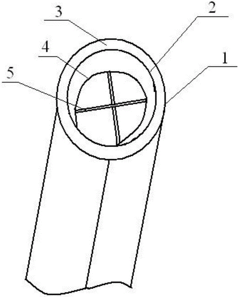
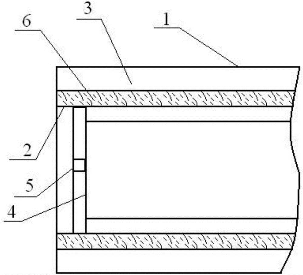
[0028] figure 1 It is a schematic diagram of a solar heat collecting tube of the present invention; as shown in the figure, a solar heat collecting tube of the present invention includes a heat collecting tube body, and the heat collecting tube body includes a heat collecting inner tube 2 and an outer jacket sleeved outside the heat collecting inner tube 2 The tube 1, the heat collecting inner tube 2 and the outer tube 1...


PUM


Abstract

The invention discloses a solar heat collecting pipe which comprises a heat collecting pipe body. The heat collecting pipe body comprises a heat collecting inner pipe and an outer sleeve, wherein the heat collecting inner pipe is sleeved with the outer sleeve. The heat collecting inner pipe and the outer sleeve are arranged coaxially. The outer wall of the heat collecting inner pipe is coated with a plurality of layers of coating films. A plurality of reinforcing ribs parallel to the axis are integrally formed on the inner wall of the heat collecting inner pipe. The space between the outer wall of the heat collecting inner pipe and the inner wall of the outer sleeve serves as a vacuum cavity. The invention further discloses a manufacturing method of the solar heat collecting pipe. By the adoption of the technical scheme, the heat utilization rate of the heat collecting inner pipe is increased through the multiple layers of coating films, the water temperature in a solar water heater is greatly increased, the influences of the application environment on the solar water heater are reduced, especially on rainy days or in winter when sunshine duration is short, the effect that the water temperature in the solar water heater meets shower requirements is guaranteed, application of the temperature compensation function is avoided, and the utilization rate of the solar water heater is increased.

Description

technical field [0001] The invention belongs to the field of solar heat utilization, and more specifically, the invention relates to a solar heat collecting tube and a manufacturing method thereof. Background technique [0002] Solar water heaters have been widely used in recent years because they use sunlight to obtain a steady stream of energy. However, many solar water heaters are affected by the environment in which they are used. In cloudy and rainy days or in winter with short sunshine hours, the solar heat collector tubes do not absorb enough heat, resulting in solar energy. The water heater cannot be used normally, and even due to the abnormal climate, the glass tube has poor resistance to rapid cooling and rapid heating, and the solar collector tube bursts. The existing technology solves the problem of low water temperature caused by insufficient sunlight by using electric energy compensation or other temperature compensation methods. , this compensation method, lim...

Claims


Application Information

Patent Timeline
Patent Type & Authority Applications(China)
IPC IPC(8): F24J2/46F24J2/48F24J2/10C23C14/08C23C14/10C23C14/06C23C14/14F24S23/70
CPCC23C14/0635C23C14/0641C23C14/08C23C14/10C23C14/14F24S23/82F24S70/25F24S70/30F24S2023/86Y02E10/40
Inventor 滕忠文
Owner 芜湖市万里达新能源有限公司
Learn More