Device for measuring retroreflection coefficient

A technology of retroreflection coefficient and retroreflection, which is applied in the direction of measuring device, scattering characteristic measurement, material analysis through optical means, etc. It can solve the problems of cumbersome testing process, low testing accuracy and bulky volume, and achieve convenient operation and small size , the effect of uniform light

Inactive Publication Date: 2016-11-16
ANHUI UNION SAFE TECH
View PDF4 Cites 2 Cited by
  • Summary
  • Abstract
  • Description
  • Claims
  • Application Information

AI Technical Summary

Problems solved by technology

Traffic signs play an important role in traffic safety, but the devices for detecting the retroreflection coefficient of these reflective signs are far behind the actual needs
Most of the existing retroreflection coefficient detection devices are indoor desktops, which have the disadvantages of bulky, cumbersome testing process, and low testing accuracy.

Method used


Image

  • Device for measuring retroreflection coefficient
  • Device for measuring retroreflection coefficient
  • Device for measuring retroreflection coefficient

Examples


Embodiment Construction

[0021] Below in conjunction with accompanying drawing, the present invention is described in further detail by embodiment:

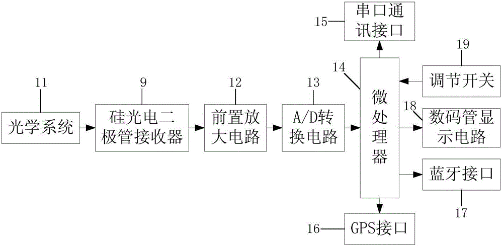
[0022] like Figure 1-Figure 4 A device for measuring retroreflection coefficient shown includes an optical system 11, a photodiode receiver 9 and a retroreflection spot processing circuit. The optical system 11 , the photodiode receiver 9 and the retroreflection spot processing circuit are all arranged in the housing 10 . The casing 10 includes an upper cover and a rear cover detachably connected with the upper cover.

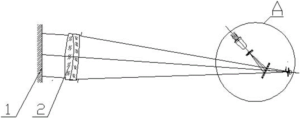
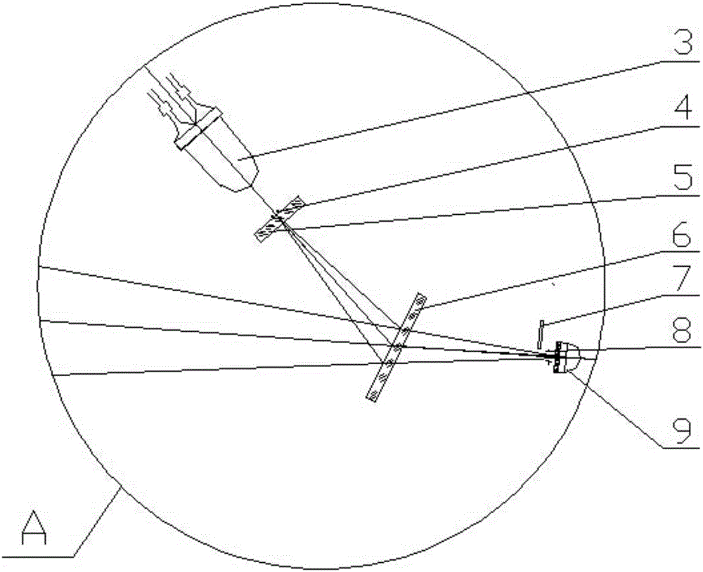
[0023] like figure 2 and image 3 As shown, the optical system includes a warm white light diode 3 , a light source aperture diaphragm 4 , a soft mirror 5 , a beam splitter 6 and an achromatic objective lens 2 . The achromatic objective lens 2 and the photodiode receiver 9 are respectively located on the left and right sides of the beam splitter 6 . The light source pinhole diaphragm is located at the center point of the focal plan...


PUM


Abstract

The invention relates to a device for measuring a retroreflection coefficient. The device comprises an optical system, a photodiode receiver and a retroreflection light spot processing circuit which are all arranged in a shell; the optical system comprises a warm white light diode, a light source small hole diaphragm, a soft light lens, a spectroscope and an achromatic objective lens, wherein the achromatic objective lens and the photodiode receiver are located on the left side and the right side of the spectroscope, and light emitted by the warm white light diode sequentially passes through the light source small hole diaphragm, the soft light lens, the spectroscope and the achromatic objective lens and then is emitted to a retroreflection light membrane layer in parallel; the retroreflection light spot processing circuit comprises a pre-amplification circuit, an A / D conversion circuit and a microprocessor. The device has the advantages of being small in size, high in precision, convenient to operate, suitable for site tests and the like.

Description

Technical field: [0001] The invention relates to the technical field of retroreflection detection, in particular to a device for measuring retroreflection. Background technique: [0002] At present, the traffic construction is developing rapidly, and the traffic signs on the road are also becoming more and more perfect. Traffic signs play an important role in traffic safety, but the devices for detecting the retroreflection coefficient of these reflective signs are far behind the actual needs. Most of the existing retroreflection coefficient detection devices are indoor desktops, which have the disadvantages of bulky, cumbersome testing process, and low testing accuracy. Invention content: [0003] The object of the present invention is to provide a device for measuring the retroreflection coefficient, which has the characteristics of small size, high precision, convenient operation and suitable for on-site testing. [0004] The technical scheme adopted in the present in...

Claims


Application Information

Patent Timeline
Patent Type & Authority Applications(China)
IPC IPC(8): G01N21/47
CPCG01N21/47G01N2021/4735G01N2201/062G01N2201/0631
Inventor 胡辉唐岩高岳巢
Owner ANHUI UNION SAFE TECH
Why Eureka
Try Eureka