
Method for testing space electromagnetic radiation interference via planar circuit

A technology for testing space and electromagnetic radiation. It is used in the measurement of interference from external sources, measurement of electricity, and measurement devices. It can solve problems such as large testing errors, changing radiation field distribution, and inability to place test probes, reducing space occupation and testing. Errors, the effect of eliminating adverse effects

Inactive Publication Date: 2016-11-16
SOUTHWEST JIAOTONG UNIV
View PDF6 Cites 4 Cited by
  • Summary
  • Abstract
  • Description
  • Claims
  • Application Information

AI Technical Summary

Problems solved by technology

In the process of testing with a field strength meter (current probe), the placement and fixation of the probe is a major difficulty in the test, especially in the case of narrow internal space and dense cables (in the case of most microwave sources), It is possible to place the test probes at all
Secondly, the placement of the probe will change the distribution of the radiation field, which will bring large errors to the test.

Method used


Image

  • Method for testing space electromagnetic radiation interference via planar circuit
  • Method for testing space electromagnetic radiation interference via planar circuit
  • Method for testing space electromagnetic radiation interference via planar circuit

Examples


Embodiment Construction

[0027] The present invention will be further described below in conjunction with accompanying drawing and specific embodiment:

[0028] The measurement steps are as follows:

[0029] 1. Prepare to access the measurement environment and connect the measurement equipment

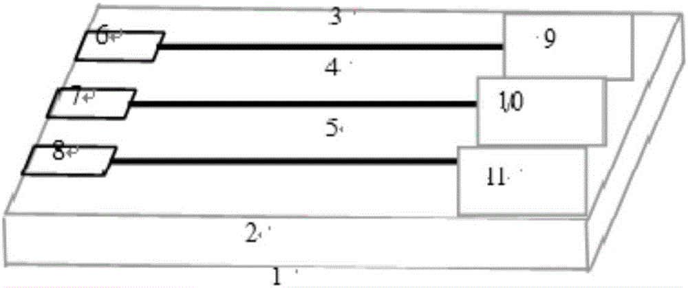
[0030] The device prepared in this embodiment includes: figure 1 The multi-cable planar test circuit, spectrum analyzer, adjustable attenuator, electric field probe, and signal generator are shown.

[0031] The multi-cable plane test circuit ( figure 1 ) placed in the test environment at the position to be tested, and the adjustable attenuator and the spectrum analyzer are connected with a coaxial cable.

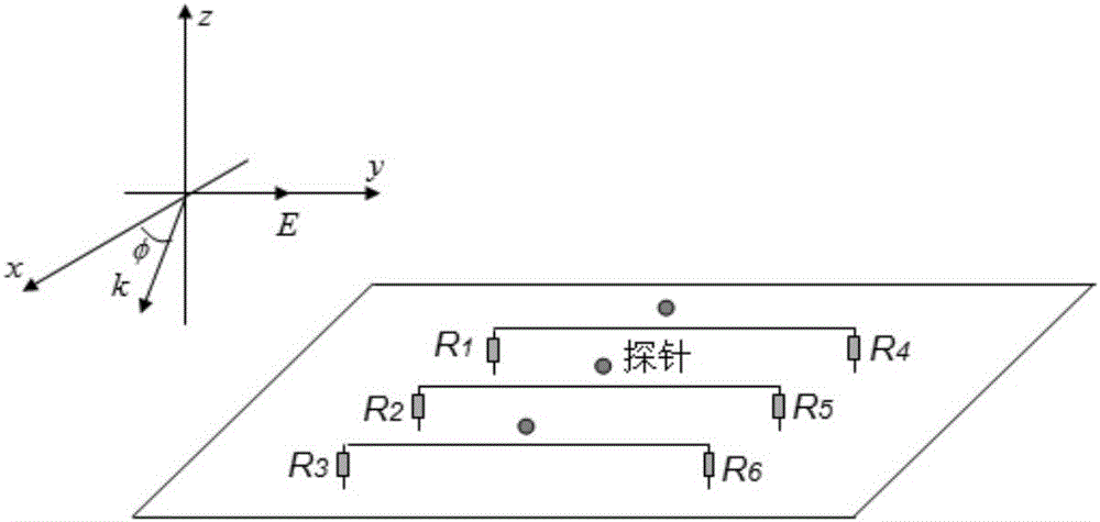
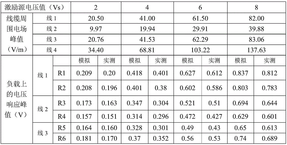
[0032] 2. Measure the voltage response of the cable load

[0033] Preset the adjustable attenuator to a larger gear, turn on the spectrum analyzer, select the measurement frequency range, observe the interference spectrum and adjust the adjustable attenuator so that the measured signal is within a reason...


PUM


Abstract

The invention discloses a method for testing space electromagnetic radiation interference via a planar circuit. The method comprises the steps of: (1) placing a planar test circuit in a region to be tested; (2) measuring voltage and current responses of loads of cables; (3) and calculating to obtain a space radiation field surrounding the cables by adopting a finite-difference time-domain method FDT in a cable and space radiation field coupling model according to the voltage and current responses of the loads of the cables obtained through test in the step 2. The method provided by the invention can solve the problem of large testing error caused by electromagnetic radiation interference signals in a testing space under the conditions that the testing space of a field intensity meter (a current probe) is small and the cables are dense. Through testing the voltage response of the cables, the surrounding space electromagnetic field is calculated, the application rage is expanded by adopting a multi-cable coupling model, the influence of reflected waves is effectively eliminated by using matched loads, the difficulty of testing the space electromagnetic field under the conditions of small internal space and dense cables is effectively solved, and the method is suitable for popularization and application in the fields of microwave technologies and electromagnetic compatibility.

Description

technical field [0001] The invention belongs to the field of microwave technology and electromagnetic compatibility, and in particular relates to a method for electromagnetic radiation interference in a planar circuit test space Background technique [0002] Electromagnetic compatibility technology is widely used in industry, science and medicine (IMS) research, and its application fields are expanding. Especially in the case of continuous wave, high power, and long-time working microwave sources, the leakage radiation of microwave space will have a fatal impact on the control circuit at this time. According to relevant literature analysis, cable coupling is the main way for space radiation to cause damage to circuit components. Therefore, in order to ensure the long-term effective operation of electronic products, it is necessary to test space electromagnetic radiation interference. [0003] The space electromagnetic radiation interference test mainly uses the standard ant...

Claims


Application Information

Patent Timeline
IPC IPC(8): G01R31/00
CPCG01R31/001
Inventor 熊祥正叶志宏廖成高明均罗杰郭晓东
Owner SOUTHWEST JIAOTONG UNIV
Learn More