Hall sensor magnetic flux test structure

A Hall sensor and test structure technology, applied in the direction of measuring magnetic variables, instruments, measuring devices, etc., can solve the problems that affect the test accuracy and results, and there is no Hall sensor magnetic field strength specification, etc., to achieve the improvement of test accuracy and increase Trigger rate effect

Active Publication Date: 2019-02-12
珠海市运泰利自动化设备有限公司
View PDF5 Cites 0 Cited by
  • Summary
  • Abstract
  • Description
  • Claims
  • Application Information

AI Technical Summary

Problems solved by technology

Therefore, the slight change of the magnetic field intensity induced by the Hall sensor will be amplified, affecting the accuracy and results of the test, and the magnitude of the magnetic field strength depends on the relative distance of the magnetic field transmitter to the Hall sensor and the influence of other external substances that can generate a magnetic field; This type of test equipment currently on the market generally only limits the triggering of the Hall sensor, but does not regulate the magnetic field strength of the trigger range of the Hall sensor.

Method used


Image

  • Hall sensor magnetic flux test structure
  • Hall sensor magnetic flux test structure
  • Hall sensor magnetic flux test structure

Examples


Embodiment Construction

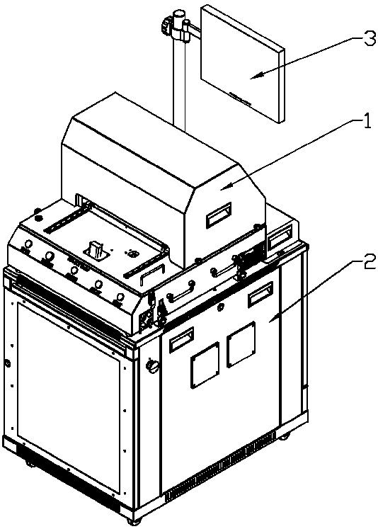
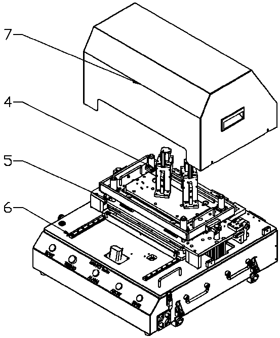
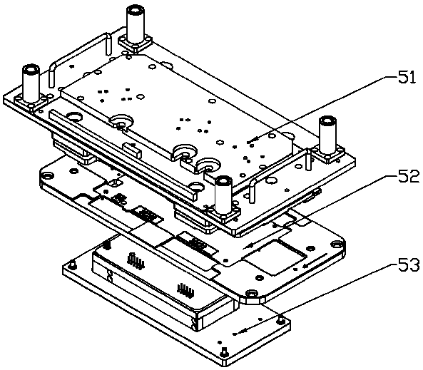
[0021] Such as Figure 1 to Figure 6 As shown, in this embodiment, the present invention includes a function test module 1, a split test cabinet 2 and a touch control system 3, and the function test module 1 and the touch control system 3 are installed in the split On the counter top of the test cabinet 2, the touch control system 3 is located on one side of the functional test module 1, and the inside of the split test cabinet 2 is provided with a circuit board and a power supply, and the functional test module 1, The split test cabinet 2 and the touch control system 3 are electrically connected to each other, the functional test module 1, the split test cabinet 2 and the touch control system 3 adopt a separate design, and Non-integrated design, and their shells are covered with steel or sheet metal cold plates or other magnetic field shielding materials to reduce the interference of the magnetic field generated by the invention itself on the Hall sensor. This is the first-le...


PUM


Abstract

The present invention discloses a Hall sensor magnetic flux test structure, and aims to provide the Hall sensor magnetic flux test structure which is compact in structure, convenient in assembly and maintenance operations and high in test accuracy. The Hall sensor magnetic flux test structure of the present invention comprises a function test module, a split type test cabinet and a touch type control system, the function test module and the touch type control system are both installed on the table-board of the split type test cabinet, and the touch type control system is located at one side of the function test module. The function test module comprises Hall sensor trigger mechanisms, an electrical property test mechanism and a motion control mechanism, the motion control mechanism is arranged on the table-board of the split type test cabinet, and the electrical property test mechanism is fixedly installed on the motion control mechanism and is equipped with two Hall sensor trigger mechanisms. The Hall sensor magnetic flux test structure of the present invention is applied to the technology field of the magnetic flux calibration test equipment of the Hall sensors.

Description

technical field [0001] The invention relates to magnetic flux calibration testing equipment for a Hall sensor, in particular to a magnetic flux testing structure for a Hall sensor. Background technique [0002] The Hall effect is a kind of electromagnetic effect. This phenomenon was discovered by the American physicist Hall in 1879 when he was studying the conduction mechanism of metals. It defines the relationship between the magnetic field and the induced voltage. When the current passes through the conductor perpendicular to the external magnetic field, the carriers are deflected, and an additional electric field is generated perpendicular to the direction of the current and the magnetic field, thereby generating a potential difference at both ends of the conductor. This phenomenon is the Hall effect, and this potential difference is also called called the Hall potential difference. However, because the Hall effect of early metal materials was too weak, it was not widely...

Claims


Application Information

Patent Timeline
Patent Type & Authority Patents(China)
IPC IPC(8): G01R33/07
CPCG01R33/07
Inventor 莫伟健何郁明
Owner 珠海市运泰利自动化设备有限公司
Why Eureka
Try Eureka