
Air chamber frequency selection surface structure

A frequency selective surface, air cavity technology, applied in electrical components, circuits, resonators, etc., can solve the problems of small frequency response curve slope, few controllable parameters, poor polarization stability, etc., to achieve rapid prototyping, wide application, The effect of improving performance

Inactive Publication Date: 2016-11-16
SOUTH CHINA UNIV OF TECH
View PDF7 Cites 5 Cited by
  • Summary
  • Abstract
  • Description
  • Claims
  • Application Information

AI Technical Summary

Problems solved by technology

[0005] 2) The invention patent application with the Chinese patent application number 201510953990.5 discloses a frequency selective surface structure based on a three-dimensional structure, such as figure 2 As shown, it solves the problems that the existing frequency selective surface with simple structure has relatively few controllable parameters, the slope of the frequency response curve is small, the polarization stability is poor, and the miniaturization is poor in practical applications.

Method used


Image

  • Air chamber frequency selection surface structure
  • Air chamber frequency selection surface structure
  • Air chamber frequency selection surface structure

Examples


Embodiment 1

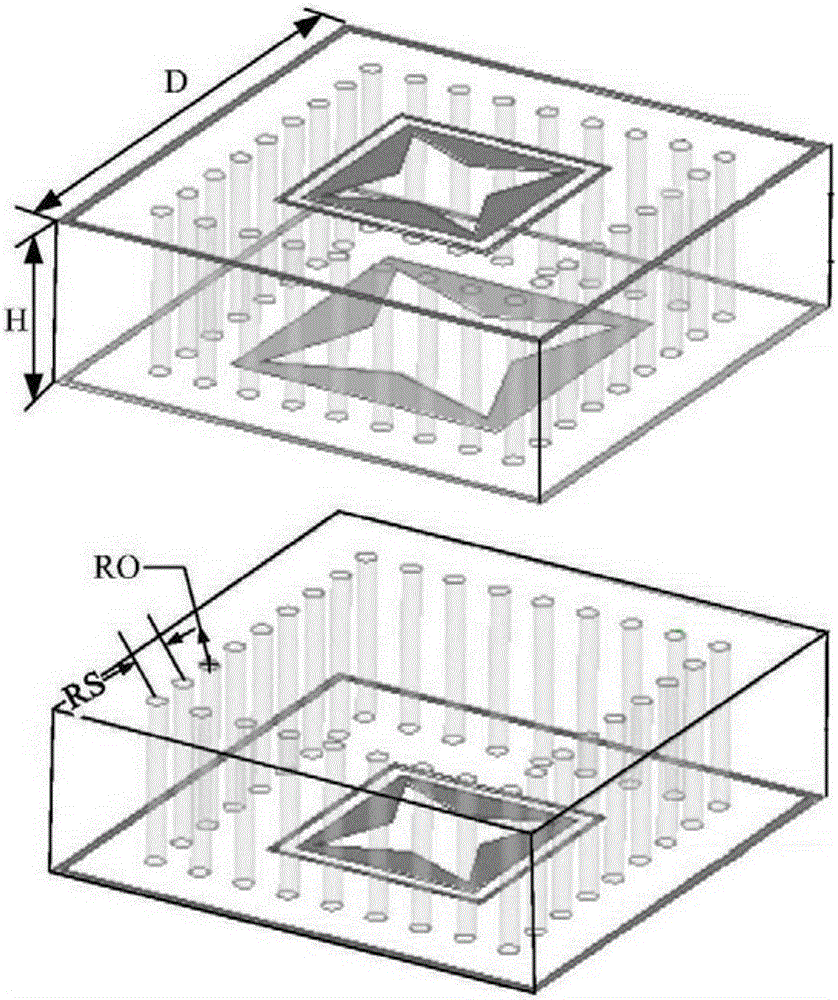
[0036] Such as Figure 4 ~ Figure 6 As shown, the frequency selective surface structure of the air cavity in this embodiment is composed of M*N identical periodic units, and each periodic unit is a cuboid structure. The front and back of the cuboid structure have a groove line, and the front groove line It is the first groove line 1, and the groove line on the opposite side is the second groove line 2. The first groove line 8 and the second groove line 9 are rectangular groove lines with a length of L and a width of W. The middle of the cuboid structure is an air cavity resonator 3, the inner and outer surfaces of the air cavity resonator 3 are surrounded by metal; wherein, M>10, N>10, due to the large number of periodic units, only shown in the figure of this embodiment The number of periodic units of 2*2.

[0037]The air cavity resonator 3 is formed by 3D printing, so it can be quickly formed, the processing is quite easy, and the precision is high; the metal is covered on ...

Embodiment 2

[0046] The main features of this embodiment are: as Figure 8 As shown, the air cavity frequency selective surface structure of the present embodiment is used as a three-frequency air cavity frequency selective surface structure, and the first groove line 1 on the front side of the cuboid structure is along the positive direction of the X axis relative to the geometric center point of the cuboid structure ( +X axis) offset distance S, and rotate angle θ to the right relative to the Y axis; the second groove line 2 on the reverse side of the cuboid structure is along the opposite direction of the X axis (-X axis) relative to the geometric center point of the cuboid structure The distance S is offset, and the angle θ is rotated to the right relative to the Y axis, that is to say, the first groove line 1 and the second groove line 2 are offset in opposite directions but rotate in the same direction. All the other are with embodiment 1.

[0047] The electromagnetic simulation cur...


PUM


Abstract

The invention discloses an air chamber frequency selection surface structure which is formed by M*N same periodic cells, each periodic cell is a cuboid structure, each of front and back surfaces of the cuboid structure is provided with a groove line, a middle part of the cuboid structure is provided with an air chamber resonator, inner and outer surfaces of the air chamber resonator are surrounded with metal, and both of M and N are greater than 10. The air chamber frequency selection surface structure is characterized by simple structure, easy-to-process property and excellent performance. The air chamber frequency selection surface structure can be used either as a single frequency medium chamber frequency selection surface structure or as a three frequency medium chamber frequency selection surface structure; the air chamber frequency selection surface structure can be applied widely and relates to many aspects of the field of electromagnetics; in a microwave band, the air chamber frequency selection surface structure can be applied to an antenna housing, a multi-frequency reflecting surface antenna, a plane high gain antenna, an electromagnetic compatible absorber, a polarizer, a waveguide filter, artificial electromagnetic material and the like.

Description

technical field [0001] The invention relates to a frequency selective surface structure, in particular to an air cavity frequency selective surface structure, belonging to the technical field of frequency selective surfaces. Background technique [0002] Frequency Selective Surface (FSS) is an infinite planar structure composed of the same patch or aperture unit arranged in two-dimensional periodicity. It has frequency selection for electromagnetic waves with different operating frequencies, polarization states and incident angles. characteristic. According to the different frequency responses to electromagnetic waves, FSS can be roughly divided into two types: one is the metal patch type, and the other is the aperture type complementary to the patch type structure, that is, slotting on the metal plate (groove line) )Structure. When the FSS is in a resonant state, the incident electromagnetic wave undergoes total reflection (the unit is a patch type) or total transmission ...

Claims


Application Information

Patent Timeline
IPC IPC(8): H01P1/20H01P7/06
CPCH01P1/20H01P7/06H01P7/065
Inventor 王世伟邓飞
Owner SOUTH CHINA UNIV OF TECH
Features
  • Generate Ideas
  • Intellectual Property
  • Life Sciences
  • Materials
  • Tech Scout
  • Unparalleled Data Quality
  • Higher Quality Content
  • 60% Fewer Hallucinations
Learn More