Turning fixture for clutch hub in automatic transmission of automobile

An automatic transmission and clutch technology, applied in the direction of the chuck, etc., can solve the problems that the clamping force of the spring chuck is not easy to control, the clamping and unloading parts are inconvenient, and the positioning accuracy of the clamping body is not high, so as to improve the positioning accuracy and process stability. The effect of ensuring the stability of processing, convenient clamping and disassembly

Active Publication Date: 2016-11-23
SHANGHAI UNIV OF ENG SCI
View PDF4 Cites 3 Cited by
  • Summary
  • Abstract
  • Description
  • Claims
  • Application Information

AI Technical Summary

Problems solved by technology

However, thin-walled parts also have disadvantages such as weak rigidity and low hardness. Under the action of cutting force, thin-walled parts are prone to vibration, resulting in unqualified machining accuracy. In addition, under the action of clamping force, thin-walled parts are also prone to vibration. out of shape
[0003] At present, the traditional clutch hub turning fixture has the following disadvantages: 1. The clamping force of the collet is not easy to control; 2. The positioning accuracy of the clamp body is not high; 3. The service life of the clamp body is short and the wear resistance is poor ; 4. It is inconvenient to install and unload parts

Method used


Image

  • Turning fixture for clutch hub in automatic transmission of automobile
  • Turning fixture for clutch hub in automatic transmission of automobile
  • Turning fixture for clutch hub in automatic transmission of automobile

Examples


Embodiment

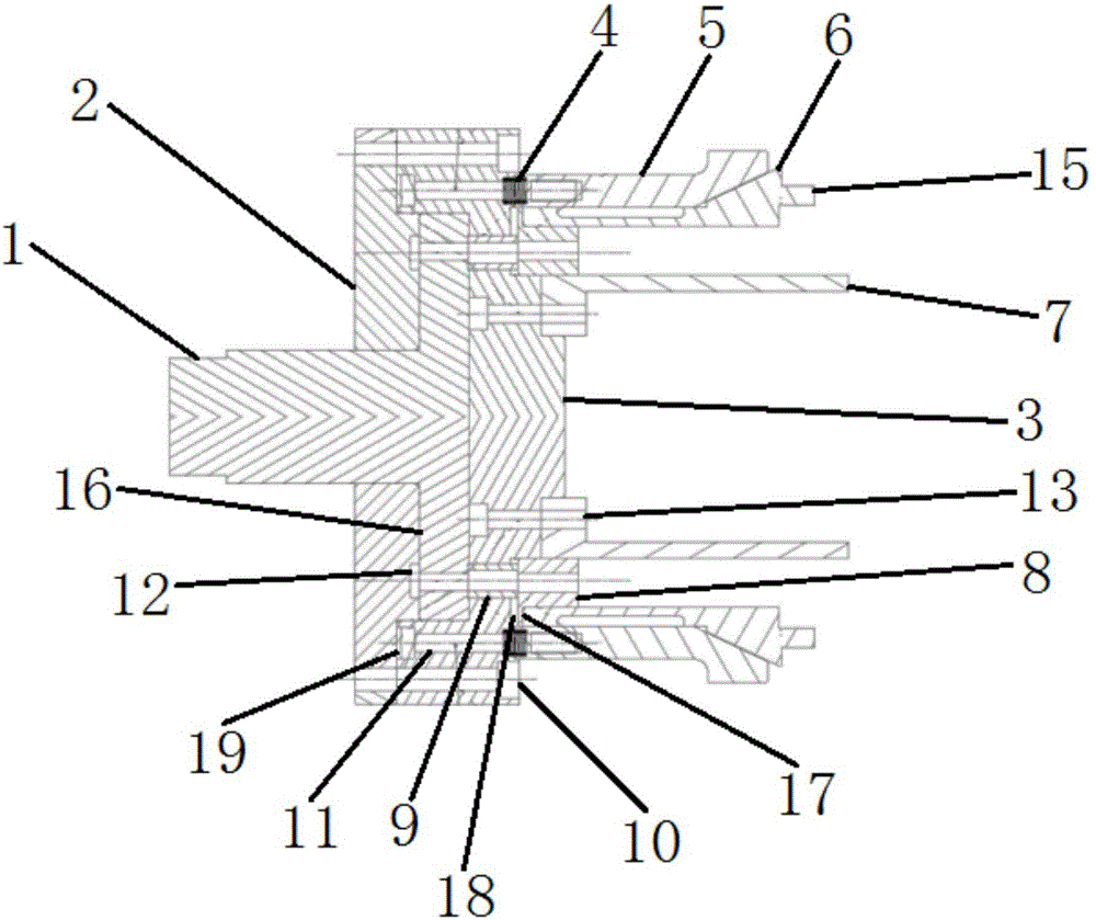
[0036] Such as figure 1 The clutch hub turning jig in the shown a kind of automobile automatic transmission comprises a jig support body, a positioning body 7 arranged at one end of the jig support body, and an elastic clamping mechanism arranged outside the positioning body 7. The elastic clamping mechanism includes a set The collet 6 outside the positioning body 7 and the housing 5 that is sleeved outside the collet 6 and adapted to the collet 6, a first elastic component is arranged between the collet 6 and the clamp support body, A second elastic assembly is provided between the housing 5 and the fixture support body, the clutch hub 14 is placed inside the collet 6, the positioning body 7 axially positions the clutch hub 14, and the housing 5 presses the collet 6 inwardly. , fix the clutch hub 14 on the fixture.

[0037] Wherein, the clamp supporting body includes a pull rod 1, a base 2 and a clip body 3, one end of the pull rod 1 is provided with a pull rod flange 16, th...


PUM


Abstract

The invention relates to a turning fixture for a clutch hub in an automatic transmission of an automobile. The fixture comprises a fixture supporting body, a positioning body arranged at one end of the fixture supporting body and an elastic clamping mechanism arranged outside the positioning body, wherein the elastic clamping mechanism comprises a spring chuck arranged outside the positioning body as well as a casing which sleeves the outside of the spring chuck and is fit with the spring chuck, a first elastic assembly is arranged between the spring chuck and the fixture supporting body, a second elastic assembly is arranged between the casing and the fixture supporting body, the clutch hub is arranged on the inner side of the spring chuck, the positioning body axially positions the clutch hub, the casing presses the spring chuck inwards, and the clutch hub is fixed on the fixture. Compared with the prior art, the clutch hub is firmly fixed on the fixture by the aid of the elasticity of a compression spring, the self-locking effect of the spring chuck and the axial positioning of the positioning body, the positioning accuracy is high, clamping and dismounting are convenient and labor-saving, and the clamping efficiency of the clutch hub is greatly improved.

Description

technical field [0001] The invention belongs to the technical field of auto parts production, and relates to a turning jig for a clutch hub in an auto automatic transmission. Background technique [0002] The automobile industry plays a pivotal role in the process of national economic development. Advances in the automotive industry can lead to the development of many related industries. Clutch hubs in automotive automatic transmissions are thin-walled parts, which have the advantages of less material, light weight, and compact structure. However, thin-walled parts also have disadvantages such as weak rigidity and low hardness. Under the action of cutting force, thin-walled parts are prone to vibration, resulting in unqualified machining accuracy. In addition, under the action of clamping force, thin-walled parts are also prone to vibration. out of shape. [0003] At present, the traditional clutch hub turning fixture has the following disadvantages: 1. The clamping force...

Claims


Application Information

Patent Timeline
Patent Type & Authority Applications(China)
IPC IPC(8): B23B31/20
CPCB23B31/208
Inventor 韩飞宋新萍周庆飞
Owner SHANGHAI UNIV OF ENG SCI
Why Eureka
Try Eureka