
Workpiece clamping and positioning mechanism and workpiece clamping and positioning assembly

A technology of clamping positioning and positioning mechanism, which is applied in the direction of manufacturing tools, metal processing equipment, auxiliary devices, etc., can solve the problems of narrow overlapping space area, large occupied space, difficult welding of welding robot hands, etc., and meet the requirement of ensuring dimensional accuracy , improve precise positioning, and ensure accessibility

Active Publication Date: 2018-05-11
GREAT WALL MOTOR CO LTD
View PDF5 Cites 4 Cited by
  • Summary
  • Abstract
  • Description
  • Claims
  • Application Information

AI Technical Summary

Problems solved by technology

[0004] However, in practice, due to the unsatisfactory positioning of the swing arm mounting bracket due to the advancement and positioning of the two cylinders, the coaxiality effect of the mounting hole of the swing arm mounting bracket and the sub-frame assembly is not easy to meet the requirements, and the positioning needs to be adjusted many times. Adjustment is time consuming
In addition, due to the limitation of the structure of the sub-frame assembly, the overlapping space between the swing arm mounting bracket and the sub-frame is narrow, and there is a space difference, and this kind of welding tool takes up a lot of space, which makes the welding torch reachable Poor performance, it is difficult for the welding robot to weld smoothly

Method used


Image

  • Workpiece clamping and positioning mechanism and workpiece clamping and positioning assembly
  • Workpiece clamping and positioning mechanism and workpiece clamping and positioning assembly
  • Workpiece clamping and positioning mechanism and workpiece clamping and positioning assembly

Examples


Embodiment Construction

[0031] It should be noted that, in the case of no conflict, the embodiments of the present invention and the features in the embodiments can be combined with each other.

[0032] The present invention will be described in detail below with reference to the accompanying drawings and examples.

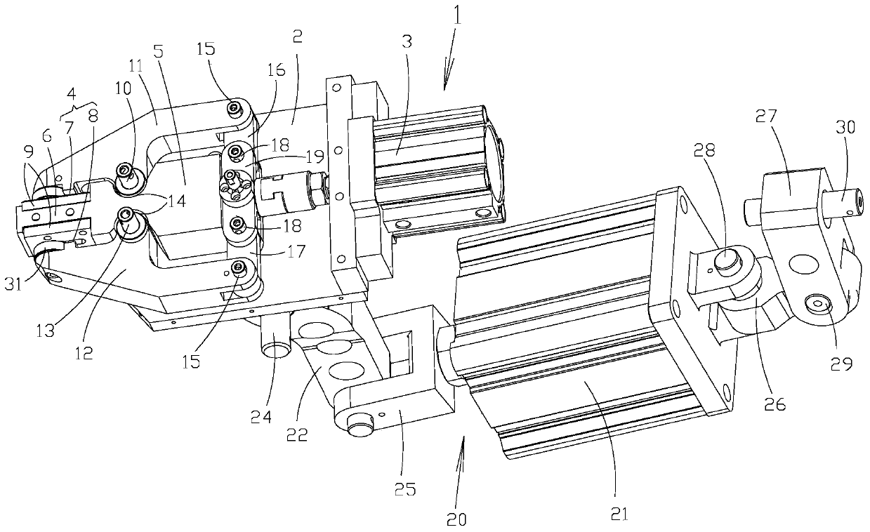
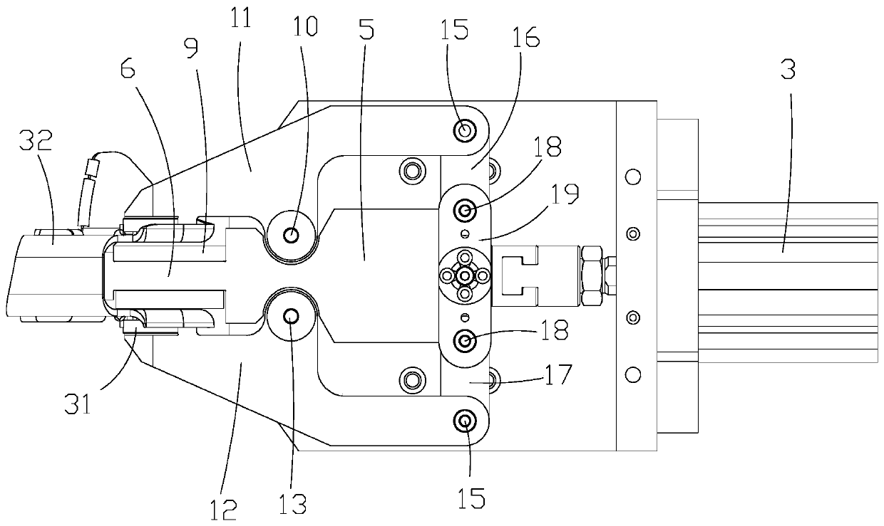
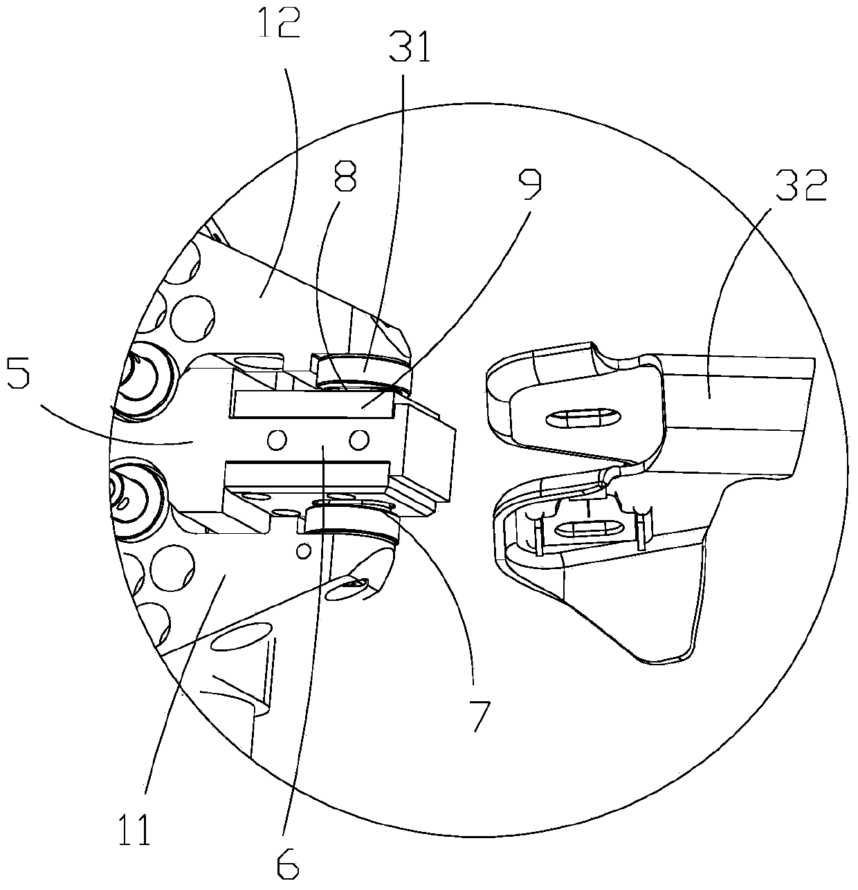
[0033] Such as figure 1 , 2 As shown in and 3, the workpiece clamping positioning mechanism of the present invention includes a clamping device 1, wherein the clamping device 1 includes a base 2, a first clamping arm 11, a second clamping arm 12 and a first power source 3, The first clamping arm 11, the second clamping arm 12 and the first power source 3 are arranged on the base 2, wherein the front end of the first clamping arm 11 and the front end of the second clamping arm 12 jointly form a The clamping port 4 of the workpiece is used to clamp the non-welding part of the workpiece, and the first power source 3 is simultaneously connected with the first clamping arm 11 and the second...


PUM


Abstract

The invention relates to the technical field of fixtures, and provides a workpiece clamping and positioning mechanism and a workpiece clamping and positioning assembly. The workpiece clamping and positioning mechanism includes a clamping device, and the clamping device includes a base, a first clamping arm, a second clamping arm and a first power source arranged on the base, and the first The front end of the clamping arm and the front end of the second clamping arm jointly form a clamping opening for clamping the workpiece, and the first power source is simultaneously connected with the first clamping arm and the second clamping arm The transmission connection is used to drive the first clamping arm and the second clamping arm to switch between the clamping position and the release position, so as to realize precise positioning of the workpiece and ensure the dimensional accuracy requirements of positioning, so as to ensure that the robotic welding torch is In the best welding condition.

Description

technical field [0001] The invention relates to the field of fixture technology, in particular to a workpiece clamping and positioning mechanism for clamping and positioning mounting brackets used for assembly and connection when vehicle assemblies are assembled with each other, and a workpiece clamping and positioning mechanism with the workpiece clamping and positioning mechanism. Workholding positioning assembly. Background technique [0002] Usually, in the production process of the vehicle suspension, the vehicle's sub-frame assembly, swing arm assembly, shock absorber assembly and other assembly parts need to be assembled and connected through corresponding opening mounting brackets. Commonly used opening mounting brackets include swing arm mounting brackets, engine mounting brackets, shock absorber mounting brackets, etc. The space position of the opening mounting bracket is narrow, and there are high requirements on the size of the assembly position and the precisio...

Claims


Application Information

Patent Timeline
Patent Type & Authority Patents(China)
IPC IPC(8): B23K37/04
Inventor 刘振京焦娜永高素英张明慧许兵辛跃宁
Owner GREAT WALL MOTOR CO LTD
Learn More