Two-panel retractable internal mold flue gas channel vibration casting machine

A technology of vibration casting machine and inner mold, which is applied in molds, ceramic molding machines, manufacturing tools, etc., can solve the problems of unsealable outer mold side plate and outer mold lower plate, cracking of the finished flue gas channel, complex structure, etc., and achieve Improve directional stability and product quality, lower cost, and improve the effect of supporting accuracy

Active Publication Date: 2018-03-16
朱志强
View PDF10 Cites 9 Cited by
  • Summary
  • Abstract
  • Description
  • Claims
  • Application Information

AI Technical Summary

Problems solved by technology

Because the inner mold is composed of shrinkable panels, the production efficiency is greatly improved, but the following problems are found in production practice: (1) The inner mold is a closed structure, which is inconvenient to maintain; (2) The inner mold is composed of 4 panels Composition, when shrinking, it will be stretched outward first, resulting in cracking of the finished flue gas channel; (3) The structure is complex and the cost is high; (4) The side plate of the outer mold and the lower plate of the outer mold cannot be sealed, and it is easy to leak slurry

Method used


Image

  • Two-panel retractable internal mold flue gas channel vibration casting machine
  • Two-panel retractable internal mold flue gas channel vibration casting machine
  • Two-panel retractable internal mold flue gas channel vibration casting machine

Examples


Embodiment

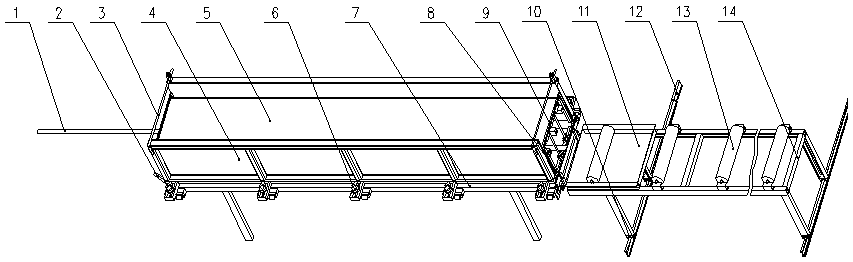
[0035] see figure 1 , the shock casting machine used to manufacture the flue gas duct of a building includes a handle, an inner mold mechanism, an outer mold mechanism, an outer mold frame 7, a mold ejection frame 14, a vibration pump, and an elastic support. The outer mold frame 7 supports the outer mold mechanism, the outer mold mechanism is placed outside the inner mold mechanism, and the flue gas channel is formed in the area clamped between the inner and outer mold mechanisms. The length of ejection frame 14 is identical with outer mold, is positioned at outer mold mechanism afterbody, and caster 10 and the guide rail 12 perpendicular to frame length direction are installed below it.

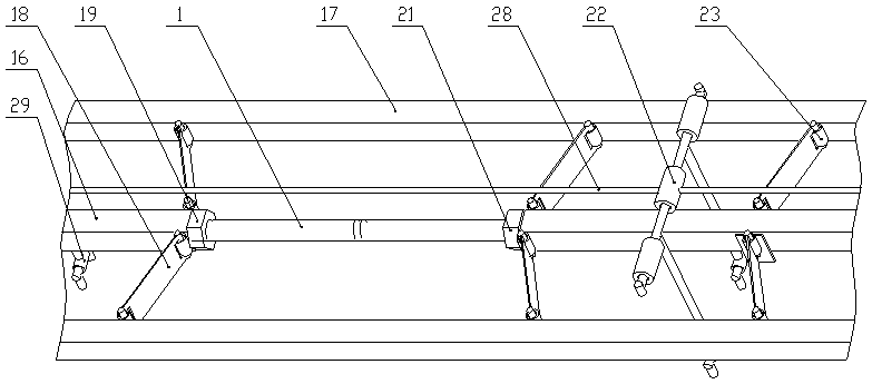
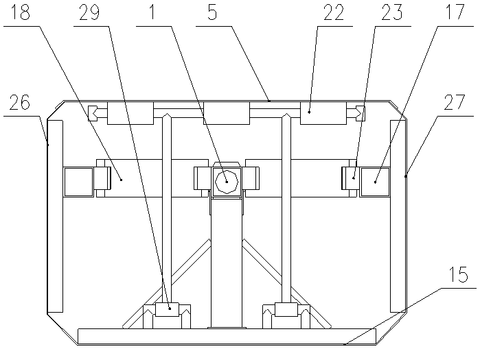
[0036] see figure 1 , figure 2 and Figure 4 , The length direction of the inner mold mechanism is consistent with the length direction of the shock casting machine, and the left and right ends are supported by the baffle plate 9 on the outer mold mechanism. The inner mold cover plate ...


PUM


Abstract

The invention relates to a vibrating casting machine for producing flue gas ducts for buildings. The vibrating casting machine comprises a handle, an internal mold mechanism, an external mold mechanism, an external mold rack, a mold-out rack, a vibrating pump and an elastic support, wherein a molding mechanism of the internal mold mechanism consists of an upper panel and a lower panel; the upper panel is linear, and the left end and the right end of the upper panel are turned downwards; the lower panel consists of a front surface, a rear surface and a bottom surface which are formed by bending a panel, the lower panel is U-shaped, and the tops of the left end and the right end of the lower panel are turned inwards to be in clearance fit with the downwardly turned parts of the upper panel; a retractable mechanism in the internal mold mechanism adopts a left-handed nut and a right-handed nut which form a pair and a plurality of sets of pull rods to realize contraction and spreading of an internal mold; a sealing strip is arranged between a side plate and a baseplate of an external mold; guiding blocks, limiting blocks and bearings are arranged at the two ends of the external mold rack; and carrier rollers are arranged at the upper part of the mold-out rack, and rollers are arranged at the lower part of the mold-out rack and are in clearance fit with guide rails.

Description

technical field [0001] The invention relates to a device for the production of flue gas ducts for buildings. Background technique [0002] At present, the production of the flue gas channel mainly uses simple molds and manual operations. The production method of the flue gas channel as described in Chinese patent 01140598 is to make the four panels that make up the flue gas channel in pieces, and then fix them and take them off after curing. mold. The method has a long production cycle and low efficiency. Another example is that the Chinese patent CN02264227.7 of semi-manual operation discloses a kind of flue gas duct mould, including bottom plate, side plate and sealing door etc., has practicability, but still is manual operation when producing flue gas duct with this mould, can't realize Efficient production, mold making cost is high, and production efficiency is low. [0003] Another example is my Chinese patents CN101596742 and CN201410102067.6, which are also vibrati...

Claims


Application Information

Patent Timeline
Patent Type & Authority Patents(China)
IPC IPC(8): B28B21/16B28B21/84B28B23/00
CPCB28B21/16B28B21/84B28B23/00
Inventor 朱志强朱德红周宇
Owner 朱志强
Why Eureka
Try Eureka