a packing machine

A baler and main body technology, applied in the field of balers, can solve the problems of cumbersome operation process, large space occupation, unrealistic, etc., and achieve the effect of avoiding the cooperation of multiple people, avoiding the deformation of the packing belt, and reliable transmission performance

Active Publication Date: 2020-02-14
温州汉德派克包装机械有限公司
View PDF6 Cites 0 Cited by
  • Summary
  • Abstract
  • Description
  • Claims
  • Application Information

AI Technical Summary

Problems solved by technology

[0003] Nowadays, balers that can use plastic belts are popular in the market, especially when using PET plastic steel belts for manual packaging. In the prior art balers, the operation process is relatively cumbersome, and one end of two overlapping PET baling belts must be pressed on the plate teeth. Next, the other end is first placed in the middle groove of the cutter assembly composed of the outer knife shell and the cutter, and then placed in the tightening groove of the winch after passing through the middle groove. During this period, the packing belt is tightened with the winch rotation. The packing belt must be removed from the winch, and the packing belt has been deformed due to the tightening of the winch, and there is a safety hazard in the second use. If cotton, fiber, foam, etc. take up a lot of space during the packing process, it is not true The straps tightened by the rotation of the outer ring of the winch are not enough to tighten the bundles
On the other hand, in the prior art, the packing machine has strict requirements on the thickness of the packing tape. Because the packing tape is too thick, the packing tape at one end pressed under the plate teeth of the packing machine will easily slip during the tightening process, and it will be laborious to cut off; If the belt is too thin, the cutting distance is not enough, it is easy to cut continuously, and it is too laborious to loosen the belt when completing the work

Method used


Image

  • a packing machine
  • a packing machine
  • a packing machine

Examples


Embodiment 1

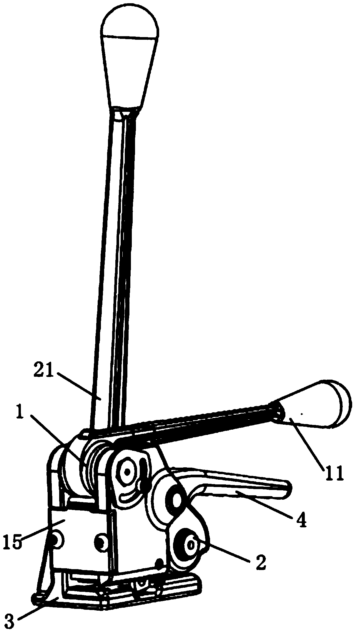
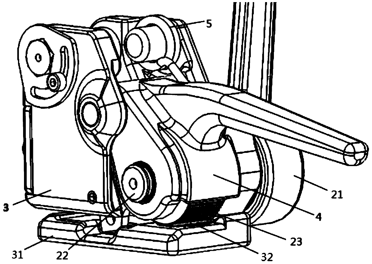
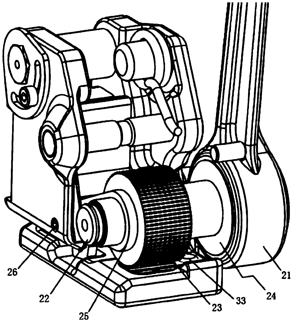
[0032] This embodiment provides, such as Figure 1-Figure 5 A baler shown includes a main body 3 with an installation space, a cutter device 1 arranged at the front end of the installation space, and a tightening device 2 arranged at the rear end of the installation space; the tightening device 2 includes The shaft seat and the tightening shaft partially accommodated in the shaft seat, the tightening wheel 23 sleeved on the tightening shaft 22, the tightening handle 1 that drives the tightening shaft 22 to rotate, and the main body 3 Corresponding to the pressure plate hanger 32 set on the tightening wheel 23, an anti-retraction structure 24 is arranged between the tightening handle 21 and the tightening shaft 22. When the tightening handle 21 rotates forward, the tightening handle 21 drives the tightening shaft 22 to rotate in conjunction with the anti-retraction structure 24; when the tightening handle 21 rotates in the opposite direction, the anti-retraction structure 24 an...


PUM


Abstract

The invention provides a packaging machine. The packaging machine comprises a body with an installation space, a cutter device arranged at the front end of the installation space, and a tightening device arranged at the rear end of the installation space. The tightening device comprises a shaft base, a tightening shaft partially contained in the shaft base, a tightening wheel arranged on the tightening shaft in a sleeving manner, a tightening handle driving the tightening shaft to rotate, and a pressing plate hanging tooth arranged on the portion, corresponding to the tightening wheel, on the body. An anti-retreat structure is arranged between the tightening handle and the tightening shaft. When the tightening handle rotates forwards, the tightening handle drives the tightening shaft to rotate in a linkage manner with the help of the anti-retreat structure. When the tightening handle rotates backwards, the anti-retreat structure and the tightening shaft are kept fixed. The packaging machine is simple in structure, the belt releasing and taking technology which is too complex and tedious in the prior art is omitted, and by arranging the anti-retreat structure, it is ensured that the packaging machine is safe and reliable during normal tightening and use.

Description

technical field [0001] The invention relates to the technical field of packing machines, in particular to a packing machine. Background technique [0002] The baler is a kind of packaging machine that wraps the packing tape on the packing object, operates the packing machine, and completes the packing work by tightening the packing tape. It is a kind of packing machine that is suitable for operation and is easy to carry. In the purposes of packing supplies, packing equipment, etc., the basic work of this packing machine is realized through the cooperation of its tightening mechanism and cutter mechanism. [0003] Nowadays, balers that can use plastic belts are popular in the market, especially when using PET plastic steel belts for manual packaging. In the prior art balers, the operation process is relatively cumbersome, and one end of two overlapping PET baling belts must be pressed on the plate teeth. Next, the other end is first placed in the middle groove of the cutter ...

Claims


Application Information

Patent Timeline
Patent Type & Authority Patents(China)
IPC IPC(8): B65B13/22B65B13/04B65B13/18B65B61/08
CPCB65B13/04B65B13/18B65B13/22B65B61/08
Inventor 吴应佩章秀祥张文勤
Owner 温州汉德派克包装机械有限公司
Why Eureka
Try Eureka