
An aluminum casing shunt device

A shunting device and aluminum casing technology, applied in the direction of conveyor control device, packaging, transportation and packaging, etc., can solve the problems of inability to realize automatic assembly line operation, aluminum casing scrapping, no automatic storage and automatic detection of the number of aluminum casings, etc., to achieve The effect of complete functions, low cost and high degree of automation

Active Publication Date: 2018-02-06
舟山市新龙电子设备有限公司
View PDF13 Cites 0 Cited by
  • Summary
  • Abstract
  • Description
  • Claims
  • Application Information

AI Technical Summary

Problems solved by technology

Otherwise, the aluminum shell will accumulate, and automatic assembly line operation cannot be realized
At present, the method adopted at this stage is to manually shunt the excess aluminum shells or directly use the device to shunt them, but there is no automatic storage and automatic detection of the number of aluminum shells. Once the operator makes a mistake, the aluminum shells will be scrapped.

Method used


Image

  • An aluminum casing shunt device
  • An aluminum casing shunt device
  • An aluminum casing shunt device

Examples


Embodiment Construction

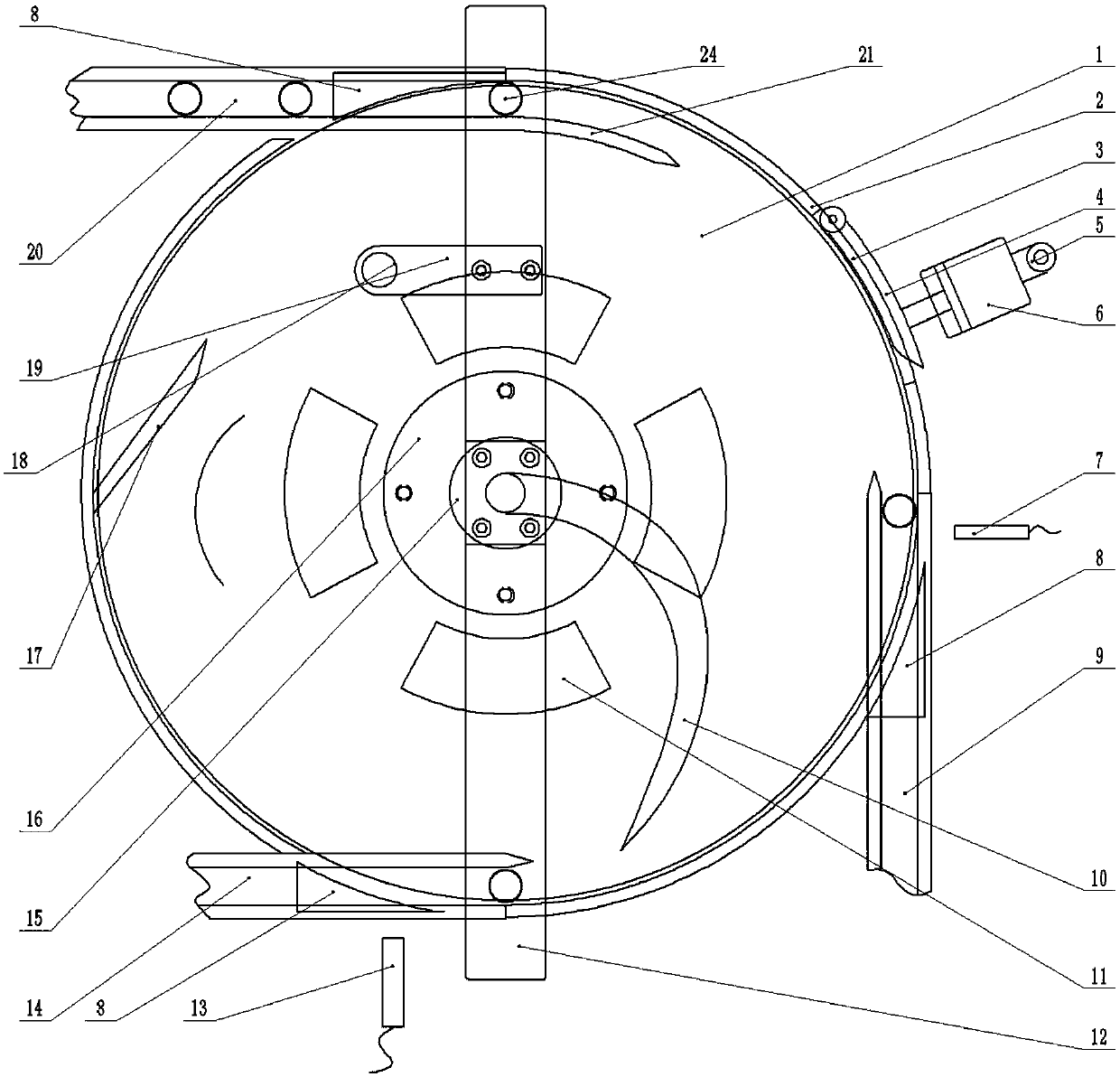
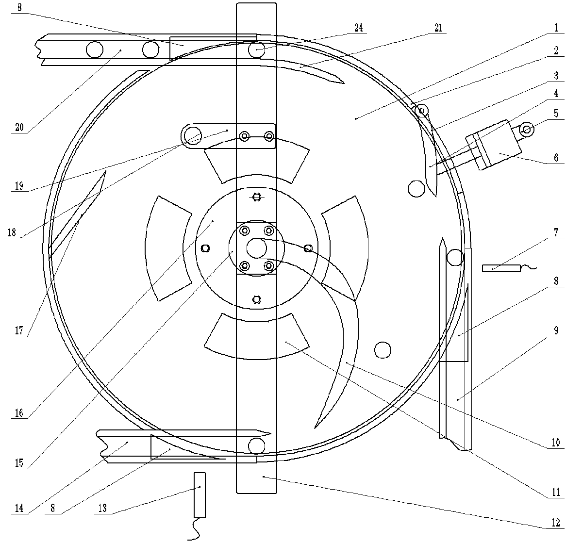
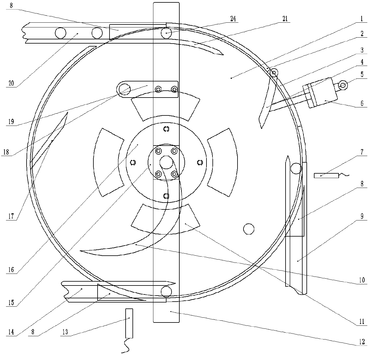
[0034] like Figure 1-4 As shown, an aluminum casing shunt device according to the embodiment of the present invention includes: the turntable 1 is connected to the motor 23 through the flange 16, and rotates clockwise with the motor; 2 Process the coaming plate hole 3 corresponding to the rotating plate 4, so that the swing arm can rotate in the coaming plate hole. The supporting plate 25 is installed under the turntable 1, which is used to install the coaming 2 and the cross bar 12; On the right side, tangent to the turntable 1, photoelectric detection I is installed on the side of the first discharge conveyor belt 9; the second discharge conveyor belt 14 is installed in front of the turntable 1, tangent to the turntable 1, and the second discharge conveyor belt 14 The photoelectric detection II 13 is installed on the side; transition plates 8 are installed at the contact points of the feed conveyor belt 20, the first discharge conveyor belt 9 and the second discharge conve...


PUM


Abstract

The invention provides an aluminum shell distributing device. A feeding conveyer belt is arranged on the back side of a rotating disk and is tangent to the rotating disk. A first discharging conveyer belt is installed on the left side of the rotating disk and is tangent to the rotating disk. A rotating plate and a rotating plate air cylinder are installed between the feeding conveyer belt and the first discharging conveyer belt. A second discharging conveyer belt is installed on the front side of the rotating disk and is tangent to the rotating disk. An adjusting plate is installed on the left side of the rotating disk. During normal transition, aluminum shells are conveyed by the feeding conveyer belt and reach an inlet of the rotating disk, the aluminum shells reach a first discharging position along with conveyance of the rotating disk, and then the aluminum shells enter a following machining device. During distribution, the machining speed of the following machining device is low and accumulation is generated, a photoelectric detector I sends a signal to enable the rotating plate to be ejected, and the aluminum shells behind the rotating plate reach a second discharging position through turning of a swing arm to enter the following machining device. When the following machining device goes wrong, a photoelectric detector II sends a signal to enable a swing arm air cylinder to drive the swing arm to rotate, and redundant aluminum shells are accumulated at the rotating disk. The aluminum shell distributing device can have certain distributing and aluminum shell storing functions.

Description

technical field [0001] The invention relates to an auxiliary device of stamping equipment, in particular to an aluminum casing flow diversion device. Background technique [0002] At present, the transportation of aluminum shells between various processing stations (such as stamping to the coding place) needs to be realized through transfer, because the speeds of processing aluminum shells of each processing device are different, especially; when the later processing speed is lower than the front When the processing speed is high, a diverter device must be installed at the transfer. Otherwise, the aluminum casing will accumulate, and automatic assembly line operation cannot be realized. At present, the method adopted at the present stage is to manually shunt the excess aluminum shells or directly use a device to shunt them, but there is no automatic storage and automatic detection of the number of aluminum shells. Once the operator makes a mistake, the aluminum shells will ...

Claims


Application Information

Patent Timeline
Patent Type & Authority Patents(China)
IPC IPC(8): B65G29/00B65G37/00B65G47/22B65G43/08B65G47/82
CPCB65G29/00B65G37/00B65G43/08B65G47/22B65G47/82B65G2201/02B65G2203/0241B65G2203/044B65G2207/14
Inventor 戴伟军
Owner 舟山市新龙电子设备有限公司
Learn More