
A wellhead sealing device for oil field pump wells

A sealing device, oilfield technology, applied in sealing/isolation, wellbore/well components, earth-moving drilling, etc., can solve problems such as hidden safety hazards, reduced production efficiency, installation and alignment difficulties, etc., to reduce time and manpower less waste, less processing and assembly difficulty, saving manpower and working time

Active Publication Date: 2019-07-05
TIANJIN BAOJUN TECH DEV
View PDF7 Cites 0 Cited by
  • Summary
  • Abstract
  • Description
  • Claims
  • Application Information

AI Technical Summary

Problems solved by technology

[0002] Most of the existing oil well wellhead sealing devices are based on polished rod integral sealers, which are very inconvenient to install, disassemble and maintain. The sealing is usually oil-producing I-shaped structure, and the packing is tightened laterally with the ejector screw. Because the pumping unit and the wellhead It is difficult to be completely concentric, and it is difficult to install and align. It is also easy to produce eccentric wear of the packing during use, causing oil leakage and polluting the environment.
If the sealing parts are damaged, the overall equipment will not be able to continue to be used. Then, in order to prevent oil leakage, the packing and polished rods need to be replaced regularly. Since the replacement of packing and polished rods requires the well to be shut down, dismantling the sealing device is time-consuming and laborious. , causing interruption of oil production and reducing production efficiency
In addition, after the polished rod is ejected or broken, the polished rod is separated from the device, causing the oil to rise rapidly and form a blowout, which not only wastes crude oil, but also poses a safety hazard

Method used


Image

  • A wellhead sealing device for oil field pump wells
  • A wellhead sealing device for oil field pump wells
  • A wellhead sealing device for oil field pump wells

Examples


Embodiment Construction

[0031] It should be noted that, in the case of no conflict, the embodiments of the present invention and the features in the embodiments can be combined with each other.

[0032] In describing the present invention, it should be understood that the terms "center", "longitudinal", "transverse", "upper", "lower", "front", "rear", "left", "right", The orientations or positional relationships indicated by "vertical", "horizontal", "top", "bottom", "inner", "outer", etc. are based on the orientation or positional relationship shown in the drawings, and are only for the convenience of describing the present invention Creation and simplified description, rather than indicating or implying that the device or element referred to must have a specific orientation, be constructed and operate in a specific orientation, and therefore should not be construed as limiting the invention. In addition, the terms "first", "second", etc. are used for descriptive purposes only, and should not be und...


PUM


Abstract

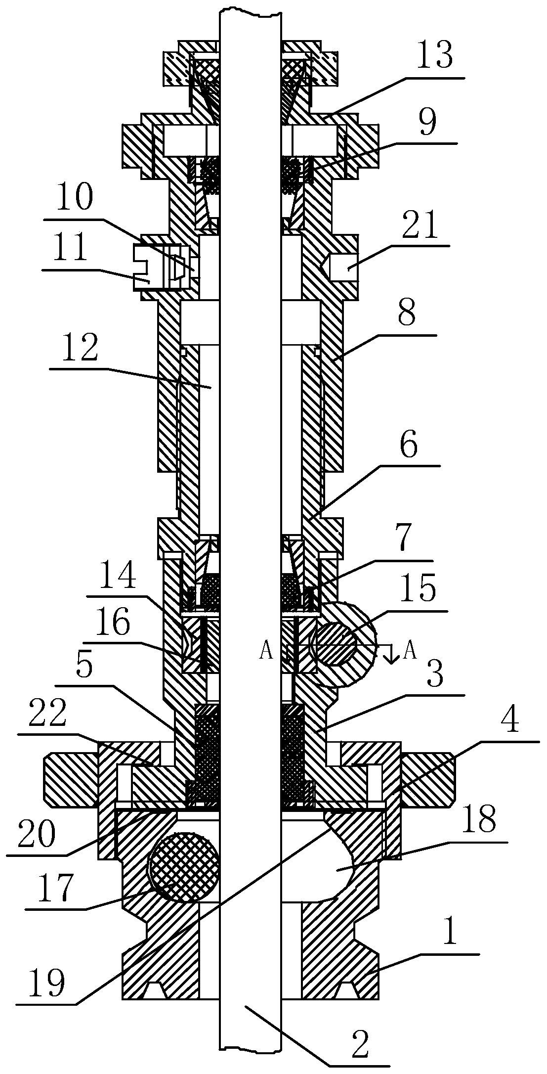
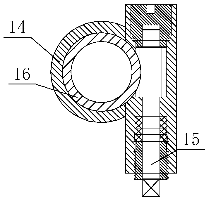
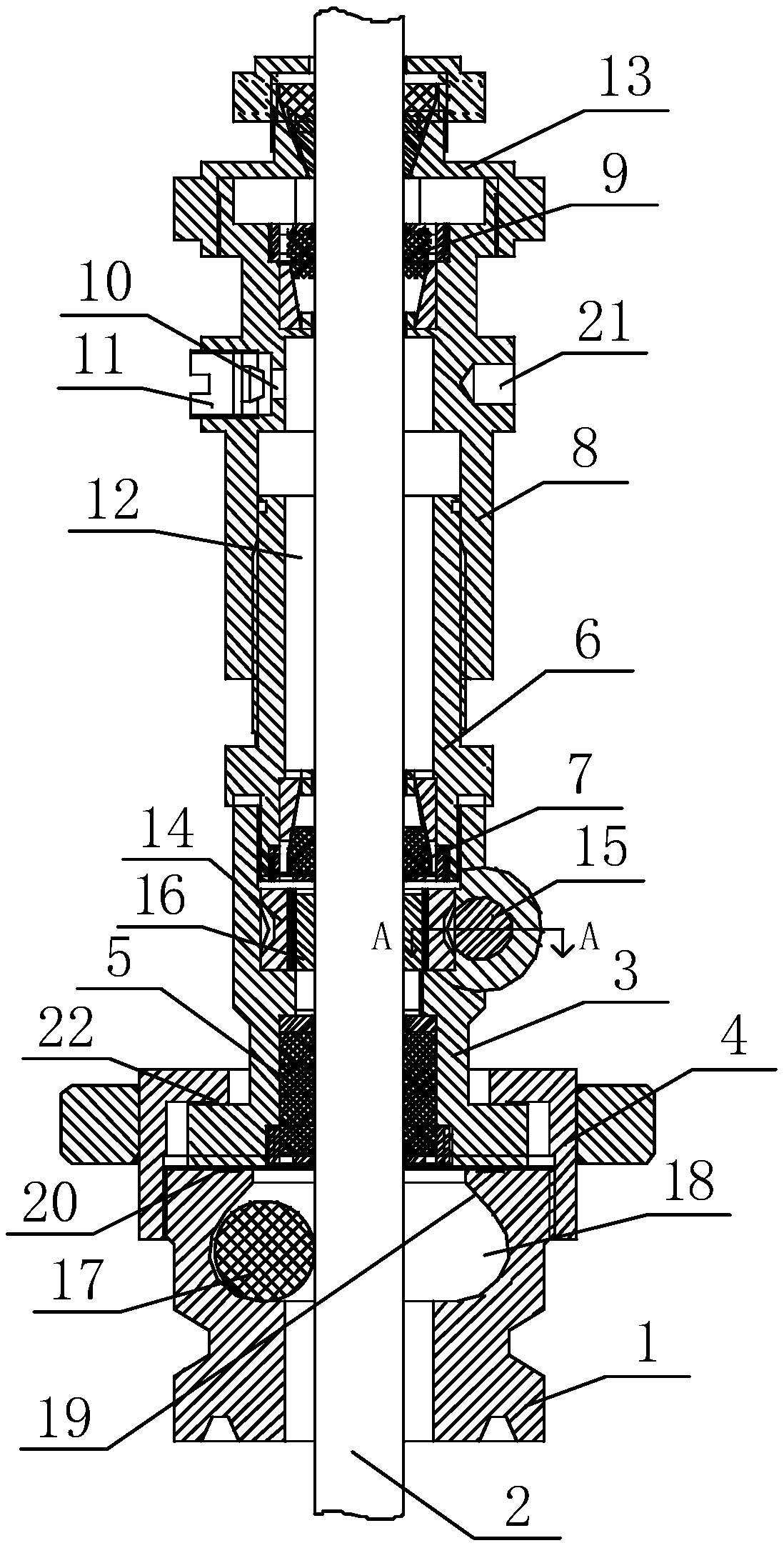
The invention provides an oil field pump well wellhead sealing device. The oil field pump well wellhead sealing device comprises a connecting base, an aligning disc, a main packing barrel and a main packing pressing sleeve; the aligning disc is fixed to the connecting base through an aligning disc gland and provided with a well plugging mechanism, and a well plugging sealing part is arranged between the aligning disc and a polish rod; the main packing barrel is connected to the upper end of the aligning disc, and a first main packing sealing part is arranged at the bottom of the main packing barrel; the main packing pressing sleeve is connected to the upper end of the main packing barrel, and a second main packing sealing part is arranged on the top of the main packing pressing sleeve; a pouring gate is formed in the upper portion of the main packing pressing sleeve and provided with a plug; communicated main packing cavities are formed between the main packing pressing sleeve and the polish rod and between the main packing barrel and the polish rod respectively. According to the oil field pump well wellhead sealing device, a worm gear is driven to rotate by spirally screwing a worm, and then a spiral pressing sleeve sleeved with the worm gear is driven to move up and down to press or loosen the well plugging sealing part; when a well needs to be plugged, the spiral pressing sleeve is driven to move downwards to press the well plugging sealing part, so that the well plugging sealing part locks the polish rod.

Description

technical field [0001] The invention belongs to the technical field of oilfield well equipment, and in particular relates to a wellhead sealing device for oilfield pump wells. Background technique [0002] Most of the existing oil well wellhead sealing devices are based on polished rod integral sealers, which are very inconvenient to install, disassemble and maintain. The sealing is usually oil-producing I-shaped structure, and the packing is tightened laterally with the ejector screw. Because the pumping unit and the wellhead It is difficult to be completely concentric, and it is difficult to install and align. It is also easy to produce eccentric wear of the packing during use, causing oil leakage and polluting the environment. If the sealing parts are damaged, the overall equipment will not be able to continue to be used. Then, in order to prevent oil leakage, the packing and polished rods need to be replaced regularly. Since the replacement of packing and polished rods r...

Claims


Application Information

Patent Timeline
Patent Type & Authority Patents(China)
IPC IPC(8): E21B33/03
CPCE21B33/03
Inventor 崔忠宝崔忠骏
Owner TIANJIN BAOJUN TECH DEV
Learn More