Hydraulic operating mechanism, ECU, clutch system and car

A control mechanism and clutch technology, applied in ECU, hydraulic control mechanism, clutch system and automobile field, can solve the problem of aggravating the driver's labor intensity, achieve low cost, meet the needs of clutch separation, and facilitate the shifting operation

Inactive Publication Date: 2016-11-23
SAIC MOTOR
View PDF6 Cites 1 Cited by
  • Summary
  • Abstract
  • Description
  • Claims
  • Application Information

AI Technical Summary

Problems solved by technology

[0004] The problem solved by the present invention is that the existing manually controlled hydraulic operating mechanism has the problem of aggravating the labor intensity of the driver.

Method used


Image

  • Hydraulic operating mechanism, ECU, clutch system and car
  • Hydraulic operating mechanism, ECU, clutch system and car
  • Hydraulic operating mechanism, ECU, clutch system and car

Examples


Embodiment Construction

[0039] In order to make the above objects, features and advantages of the present invention more comprehensible, specific embodiments of the present invention will be described in detail below in conjunction with the accompanying drawings.

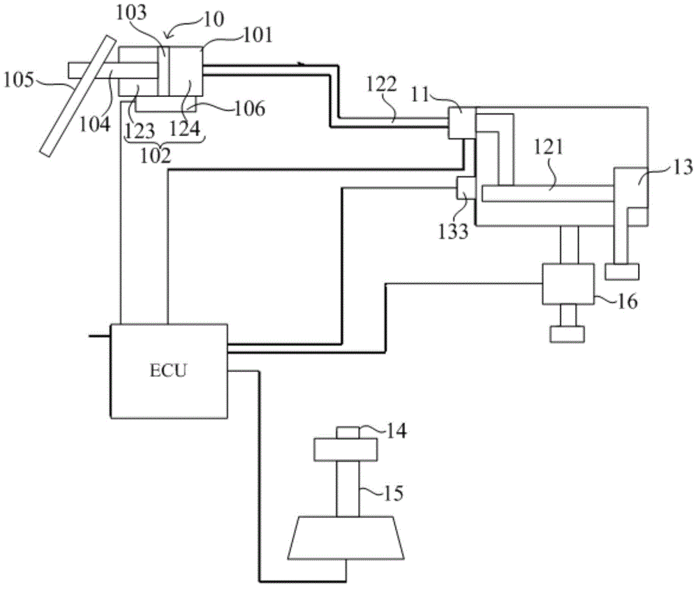
[0040] refer to figure 2 , the hydraulic control mechanism of the present embodiment includes:

[0041] clutch separation auxiliary cylinder 10;

[0042] The control valve 11 has an oil inlet, an oil outlet and an oil drain (not shown in the figure), the oil inlet is connected to the mechanical oil pump 13 through the main oil passage 121, and the oil outlet is connected to the clutch release pair through the hydraulic oil passage 122 Cylinder 10, the drain hole leads to the oil pan;

[0043] The switch device 14 is arranged on the shift lever 15, and is used to control the switching of the oil circuit of the control valve 11, so that the oil outlet hole communicates with the oil inlet hole to charge oil to the clutch release auxiliary ...


PUM


Abstract

The invention discloses a hydraulic operating mechanism, an ECU, a clutch system and a car. The hydraulic operating mechanism comprises a clutch separation assistant cylinder, a control valve and a switch device. The control valve is provided with an oil inlet, an oil outlet and an oil discharging hole, the oil inlet communicates with an engine oil pump, and the oil outlet communicates with the clutch separation assistant cylinder. The switch device is used for controlling the oil outlet and the oil inlet of the control valve to communicate through the ECU so that the clutch separation assistant cylinder can be filled with oil, and controlling the oil outlet and the oil discharging hole to communicate so that oil can be discharged from the clutch separation assistant cylinder. The hydraulic operating mechanism controls a clutch to be disengaged and engaged through the switch device in cooperation with the control valve. In addition, during gear shifting each time, a driver can control disengagement of the clutch by operating the switch device, foot action is avoided, the gear shifting operation is convenient, and the labor intensity of the driver is relieved.

Description

technical field [0001] The invention relates to the technical field of automobiles, in particular to a hydraulic control mechanism, an ECU, a clutch system and an automobile. Background technique [0002] In existing cars with manual transmission, refer to figure 1 , The hydraulic control mechanism includes: a clutch pedal 1, a master cylinder 2 connected to the pedal 1 through a push rod, and a clutch separation slave cylinder 3 connected to the master cylinder 2 through a hydraulic pipe 4. When shifting gears, first, the driver has to step on the clutch pedal 1, and the clutch pedal 1 drives the push rod of the master cylinder 2 to move, so that the hydraulic oil in the master cylinder 2 flows to the clutch release slave cylinder 3 through the hydraulic pipe 4 to realize clutch release. Then, push the shift lever to switch to the required gear; finally, slowly release the clutch pedal 1, so that the hydraulic oil in the clutch separation auxiliary cylinder 3 flows to the ...

Claims


Application Information

Patent Timeline
Patent Type & Authority Applications(China)
IPC IPC(8): F16D48/02F16D48/00F16H61/02
Inventor 霍宏煜艾维全
Owner SAIC MOTOR
Why Eureka
Try Eureka