Stove burner

A technology for burners and stoves, which is applied to burners, gas fuel burners, combustion methods, etc., can solve the problems of easy flame overflowing from the bottom of the pan, increased cost, and difficulty in maintaining thermoelectricity, so as to increase residence time and contact area, reduce Processing and material costs, effect of reduced contaminated area

Inactive Publication Date: 2016-11-23
NINGBO FOTILE KITCHEN WARE CO LTD
View PDF8 Cites 2 Cited by
  • Summary
  • Abstract
  • Description
  • Claims
  • Application Information

AI Technical Summary

Problems solved by technology

The above-mentioned existing cooker burners all have the following problems: 1. After the inner ring fire and the outer ring fire are designed separately, the flame-stabilizing structure of the inner ring fire cover and the flame-stabilizing structure of the outer ring fire cover need to be designed respectively, so that the entire burner The structure is relatively complicated, the cost increases, and the flame stabilization effect is not ideal, and the flame stabilization hole is easy to block. Once the flame stabilization hole is blocked, it is easy to cause fire failure, ignition failure, and thermocouple is difficult to maintain and the flame is turned off.
2. Due to the problem of inner and outer ring fires, in order to fully burn the inner ring fire, it is necessary to design a secondary air inlet to supplement the inner ring fire. At present, the burners on the market mainly use two ways to replenish from the chassis and from the top of the panel. Solve the problem of secondary air intake. For the burner that supplements the secondary air from the chassis, the existence of the secondary air intake will easily cause the overflow to flow into the chassis. For the burner that supplements the secondary air from the top of the panel, it will cause secondary The air inlet is not easy to clean
3. The design structure of the inner and outer ring fires requires enough secondary air inlets, so the diameter of the burner cannot be made small, generally above 100mm. In this way, the flame is easy to overflow the bottom of the pot during actual use, making the contact time between the high-temperature flue gas and the bottom of the pot And the area is reduced, the heat loss is large, and the thermal efficiency is low

Method used


Image

  • Stove burner
  • Stove burner
  • Stove burner

Examples


Embodiment Construction

[0020] The present invention will be further described in detail below in conjunction with the accompanying drawings and embodiments.

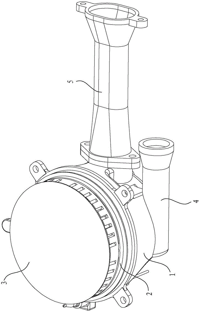
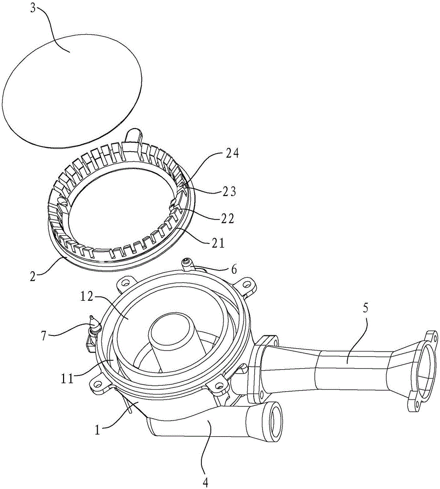
[0021] Such as Figure 1 to Figure 5 As shown, the cooker burner in this embodiment includes a burner head 1, a fire cover 2, a cover plate 3, an outer ring gas injection tube 4, an inner ring gas injection tube 5, an ignition needle 6, a thermocouple 7 and other components.

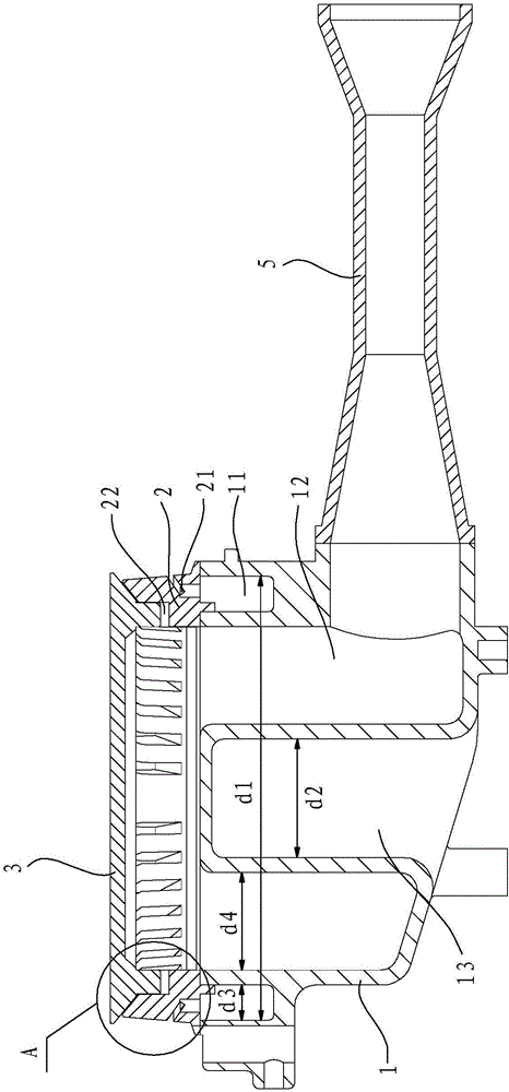
[0022] The burner head 1 has an outer ring cavity 11, an inner ring cavity 12 and a cylindrical cavity 13. The cylindrical cavity 13 is concave upward from the bottom of the burner head 1, and the cylindrical cavity 13 is located in the inner ring cavity 12 Central. The cylindrical cavity 13 acts as a flow diversion, so that the air flow uniformity in the burner 1 is better, and the gas mixing effect is better, and a temperature sensor can also be installed in the cylindrical cavity 13 to detect the burner.

[0023] The outer ring gas injection pipe 4 communicates with...


PUM


Abstract

A stove burner comprises a furnace head, an outer-ring gas ejector pipe, an inner-ring gas ejector pipe and a burner cap, wherein the furnace head comprises an outer-ring cavity and an inner-ring cavity; the outer-ring gas ejector pipe communicates with the outer-ring cavity; the inner-ring gas ejector pipe communicates with the inner-ring cavity; and the burner cap is mounted on the furnace head. The stove burner is characterized in that the burner cap comprises a lower-ring flame channel communicating with the outer-ring cavity; a cover plate is arranged on the burner cap; an upper-ring flame channel communicating with the inner-ring cavity is formed between the cover plate and the burner cap; and in addition, the lower-ring flame channel is positioned below the upper-ring flame channel. After the stove burner provided by the invention adopts the upper-ring and lower-ring flame design, the flame stabilizing effect can be well achieved by adjusting the primary air coefficient of lower-ring flame, and secondary air can be directly supplemented; not only is the supplementing effect good, but also the problem that an overflowing liquid flows into a baseplate through a secondary air hole, and then the secondary air hole is difficult to clean can be solved; and in addition, the diameter of the stove burner is relatively small, so that is not only the heat efficiency improved, but also the stove burner is easier to clean.

Description

technical field [0001] The invention relates to a burner, in particular to a cooker burner. Background technique [0002] Existing cooker burners generally include a burner and an inner ring fire cover and an outer ring fire cover installed on the burner. and outer ring fire. The above-mentioned existing cooker burners all have the following problems: 1. After the inner ring fire and the outer ring fire are designed separately, the flame-stabilizing structure of the inner ring fire cover and the flame-stabilizing structure of the outer ring fire cover need to be designed respectively, so that the entire burner The structure is relatively complicated, the cost increases, and the flame stabilization effect is not ideal, and the flame stabilization hole is easy to block. Once the flame stabilization hole is blocked, it is easy to cause fire failure, ignition failure, and thermocouple difficult to maintain and flameout phenomenon. 2. Due to the problem of inner and outer ring ...

Claims


Application Information

Patent Timeline
Patent Type & Authority Applications(China)
IPC IPC(8): F23D14/00F23D14/58F23D14/46
CPCF23D14/00F23D14/46F23D14/58
Inventor 章建锋徐强茅忠群诸永定蔡国汉郑军妹
Owner NINGBO FOTILE KITCHEN WARE CO LTD
Why Eureka
Try Eureka