
Ultrasonic flue gas flowmeter and sensor noise abatement device thereof

A technology of muffler device and flue gas flow, applied in measurement device, measurement flow/mass flow, liquid/fluid solid measurement, etc., can solve the problems of low signal-to-noise ratio, affecting the accuracy of detection results, etc., and achieve a wide range of industrial value Effect

Pending Publication Date: 2016-11-23
SHENZHEN THETA INSTR CO LTD
View PDF7 Cites 1 Cited by
  • Summary
  • Abstract
  • Description
  • Claims
  • Application Information

AI Technical Summary

Problems solved by technology

[0006] The higher the noise component generated by the residual vibration of the connecting rod itself, the lower the signal-to-noise ratio (SZ), which affects the accuracy of the test results

Method used


Image

  • Ultrasonic flue gas flowmeter and sensor noise abatement device thereof
  • Ultrasonic flue gas flowmeter and sensor noise abatement device thereof
  • Ultrasonic flue gas flowmeter and sensor noise abatement device thereof

Examples


Embodiment

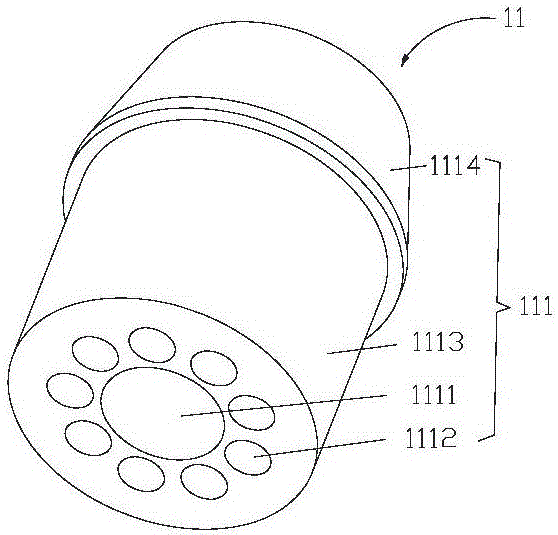
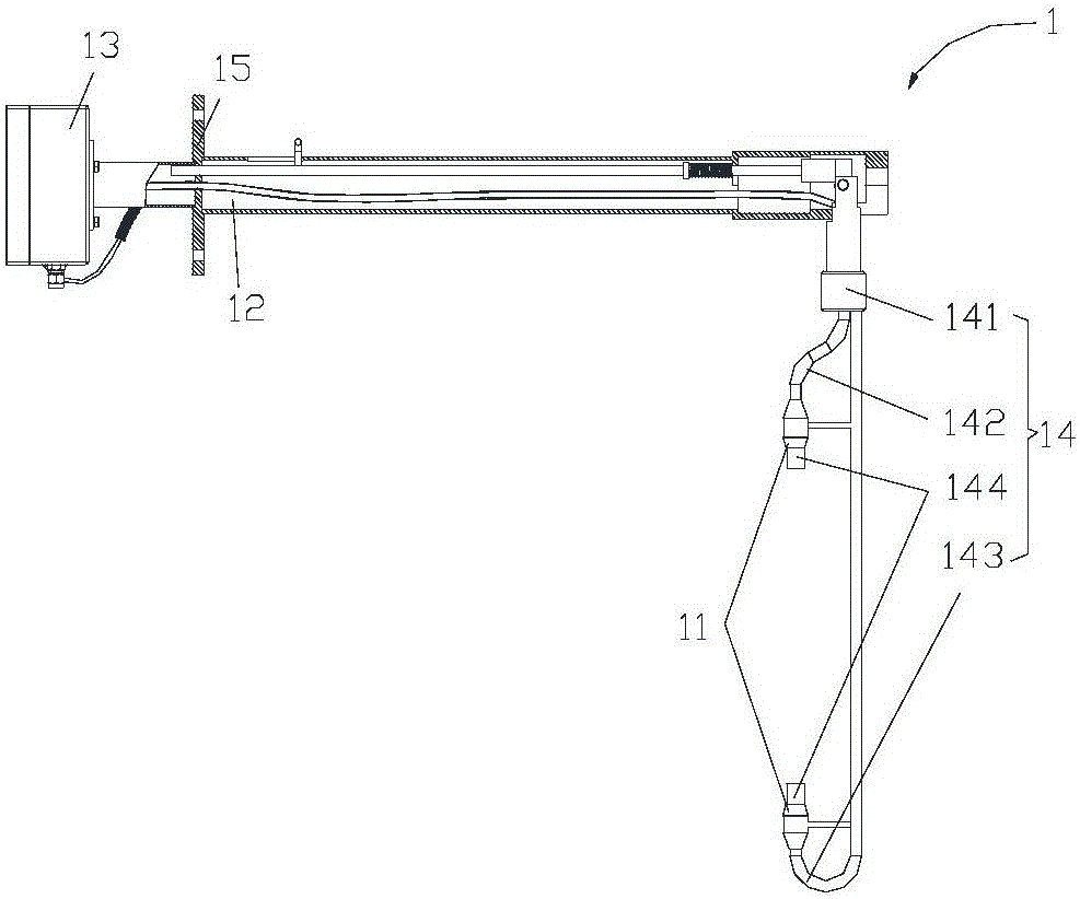
[0036] The embodiment of the present invention provides a noise reduction device 11 of an ultrasonic flue gas flowmeter 1, including a noise reduction device body 111; the noise reduction device body 111 is a cylindrical noise reduction device body 111; The device body 111 is provided with a first through hole 1111 and a second through hole 1112; the first through hole 1111 and the second through hole 1112 both pass through the muffler body 111 along the axial direction of the muffler body 111 .


PUM


Abstract

The invention provides an ultrasonic flue gas flowmeter and a sensor noise abatement device thereof. The noise abatement device comprises a noise abatement device body. The noise abatement device body is cylindrical. A first through hole and a second through hole are formed in the noise abatement device body. The first through hole and the second through hole penetrate through the noise abatement device body in the axial direction of the noise abatement device body. The noise abatement device attenuates complementary energy sent by a sensor. The noise abatement device can select a vibration reduction material and absorb complementary energy of the sensor, so that the SN ratio during measuring is increased. Meanwhile, due to the fact that the second through hole is formed in the noise abatement device, the noise abatement device body is more uniform and stable in structure, the surface area of the noise abatement device is greatly increased due to the through holes, and the sensor complementary energy absorbing capacity is effectively improved. The noise abatement device can be made of high temperature silica gel materials, the vibration reduction effect is better, the corrosion resistance is strong, and the detection device can stably work under high temperature and high humidity for a long time.

Description

technical field [0001] The invention relates to the field of detection equipment, in particular to an ultrasonic flue gas flowmeter and a noise elimination device for a sensor thereof. Background technique [0002] Accurate detection of gaseous and particulate matter emissions is a problem that many regulatory agencies attach great importance to. At present, most of them are used in the continuous emission monitoring system (Continuous Emission Monitoring System, CEMS) of thermal power plants and power plants. There are many difficulties and problems: high temperature, high dust, high moisture, negative pressure and strong corrosion, etc.; the working conditions are usually: the temperature of the flue gas medium is about 150 ℃, and the primary or secondary air of the thermal power plant is generally at 200 °C, some are about 400 °C, the existing methods of measuring flow mainly include: [0003] Pitot tube pressure difference method: Calculate the flow rate by measuring th...

Claims


Application Information

Patent Timeline
Patent Type & Authority Applications(China)
IPC IPC(8): G01F1/66
CPCG01F1/662
Inventor 宾荣权唐国栋
Owner SHENZHEN THETA INSTR CO LTD
Learn More