
Laser Array High Speed ​​Space Tracking System

A space tracking and laser array technology, which is applied to radio wave measurement systems, instruments, measurement devices, etc., can solve the problems of tracking speed, measurement range, ease of portability and erection, and insufficient implementation cost, and achieves low cost, low cost, and low cost. The effect of high tracking and positioning accuracy and convenient erection

Inactive Publication Date: 2019-02-12
BEIJING JIAOTONG UNIV
View PDF3 Cites 0 Cited by
  • Summary
  • Abstract
  • Description
  • Claims
  • Application Information

AI Technical Summary

Problems solved by technology

[0016] In view of the defects existing in the prior art, the object of the present invention is to provide a laser array high-speed space tracking system to overcome the deficiencies of the existing space tracking system in terms of tracking speed, measurement range, portability, ease of erection, and implementation cost

Method used


Image

  • Laser Array High Speed ​​Space Tracking System
  • Laser Array High Speed ​​Space Tracking System
  • Laser Array High Speed ​​Space Tracking System

Examples


Embodiment Construction

[0061] The present invention will be described in further detail below in conjunction with the accompanying drawings.

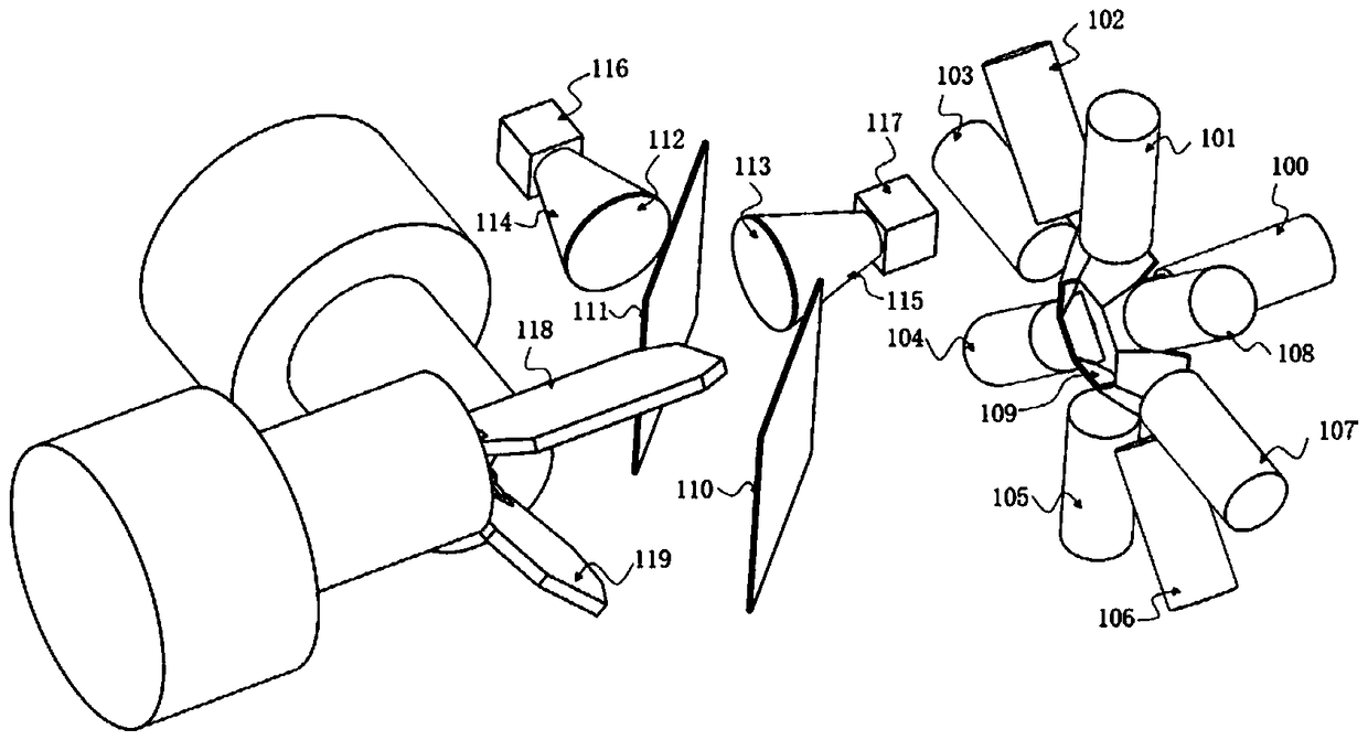
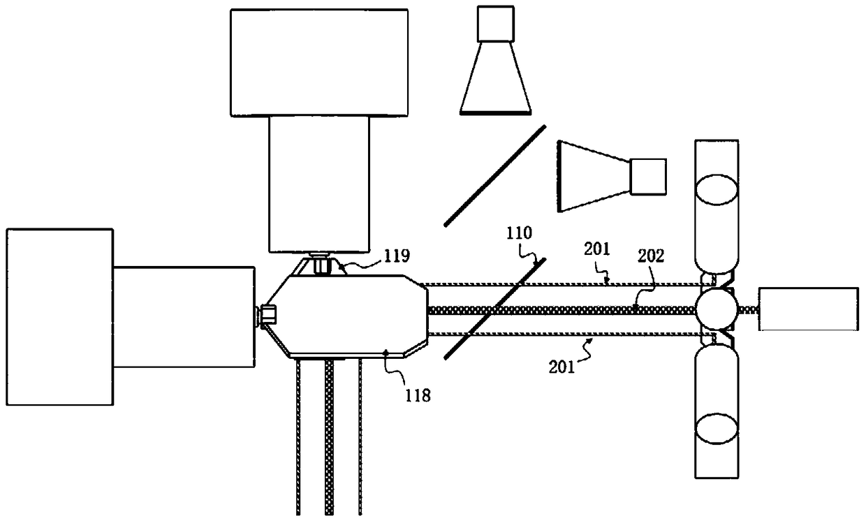
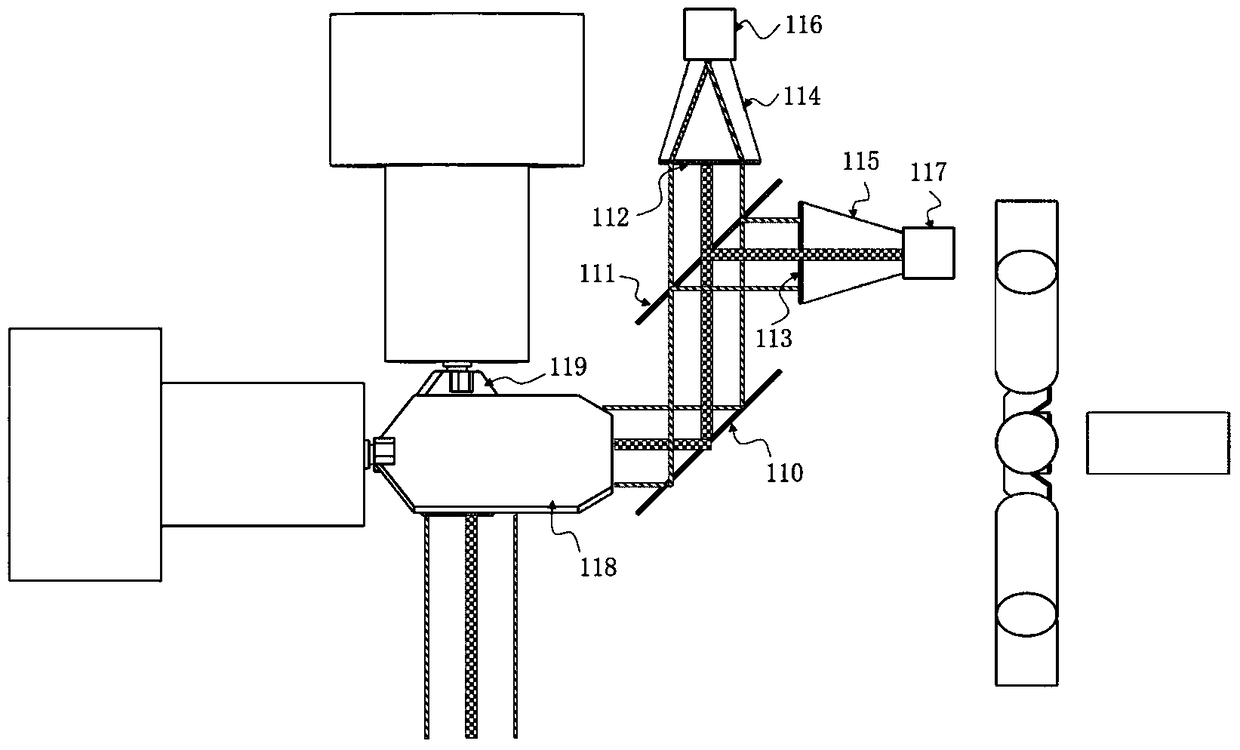
[0062] like Figure 1~6 As shown, the laser array high-speed space tracking system of the present invention can be used to track and locate one or more target balls whose surfaces are evenly covered with retroreflective materials. The core components of the system include:

[0063] beam recombination module 109,

[0064] A collimated laser 100 of A wavelength is arranged on the rear side of the beam recombination module 109,

[0065] Along the beam recombination module 109 circumferential direction, be provided with more than 3 collimated lasers of B wavelength ( Figure 1~6 Take the case where 8 collimated lasers of B wavelength are arranged along the circumference of the beam recombination module 109 as an example), the collimated lasers of each B wavelength are evenly distributed at equal intervals,

[0066] A first beam splitter 110 is provided on the ...


PUM


Abstract

The present invention relates to a laser array high-speed space tracking system. The laser array high-speed space tracking system comprises a light beam combination module; an A-wavelength collimating laser is arranged at the rear side of the light beam combination module; more three B-wavelength collimating lasers are evenly distributed along the circumferential direction of the light beam combination module; a first light splitting sheet of which the light splitting ratio is 50% is arranged at the front side of the light beam combination module; an included angle between the first light splitting sheet and the front end surface of the light beam combination module is 45 degrees; and a second light splitting sheet of which the splitting ratio is 50% is arranged at the right side of the first light splitting sheet; the second light splitting sheet is parallel to the first light splitting sheet; a first photoelectric detection module set is arranged at the right side of the second light splitting sheet; a second photoelectric detection module set is arranged at the rear side of the second light splitting sheet; and a two-dimensional scanning head is arranged at the front side of the first light splitting sheet. The tracking system of the invention is small size, convenient to erect and low in realization cost. With the system adopted, single-station measurement can be realized; one or a plurality of passive reflection type target balls can be captured with high precision in a wide range, and the spatial coordinate information of the passive reflection type target balls can be obtained with high repetition frequency. The system has high tracking and positioning accuracy and high repetition frequency.

Description

technical field [0001] The invention relates to the technical field of high-speed space tracking and positioning, in particular to a laser array high-speed space tracking system. Background technique [0002] The existing high-precision space tracking systems mainly include laser trackers and multi-eye motion capture systems. [0003] The working principle of the existing laser tracker is: a single-point collimated laser irradiates a target ball with retro-reflection characteristics, and then uses a two-dimensional PSD unit to detect the return beam reflected by the target ball, and drives it according to the deviation of the spot center of the return beam. The servo pan-tilt rotates to keep the laser tracker irradiating the center of the target ball. At the same time, the laser interferometry is used to measure the distance, and the spatial position of the target is obtained from the spherical coordinates. This scheme has the following disadvantages: [0004] First, since...

Claims


Application Information

Patent Timeline
Patent Type & Authority Patents(China)
IPC IPC(8): G01S17/66
CPCG01S17/66
Inventor 周彦钊
Owner BEIJING JIAOTONG UNIV
Learn More