
Winding method of a high voltage coil

A high-voltage coil and winding method technology, applied in the field of transformers, can solve the problems of difficult welding, burning coils, easy falling of welding, etc., and achieve the effects of avoiding high welding difficulty, enhancing reliability, and ensuring reliability.

Active Publication Date: 2017-12-15
NINGBO AUX HIGH TECH
View PDF5 Cites 0 Cited by
  • Summary
  • Abstract
  • Description
  • Claims
  • Application Information

AI Technical Summary

Problems solved by technology

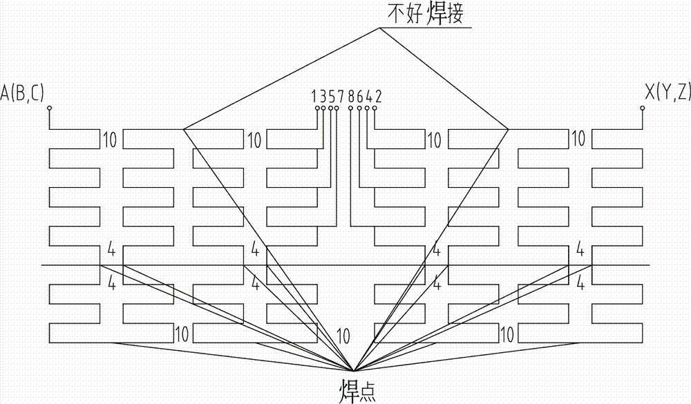
[0004] The current transformer high-voltage coil adopts a traditional structure, that is, a structure in which the high-voltage coils are evenly arranged. When this structure is used in conventional 10kV products, due to the low voltage level, the two sets of high-voltage coils are divided into four sections. The structure winding can meet the performance requirements according to this, but for 35kV and above products, due to the high voltage, under the premise of ensuring partial discharge, each high-voltage coil must ensure that the number of segments is 8-10 or more. , and with the increase of capacity, the number of air channels increases, resulting in more welding points in the high-voltage coil, and at the same time, some positions are difficult to weld, and a welding point becomes a hidden danger if it is not handled properly; see figure 1 It is a conventional coil structure, and there are 14 welding points outside the tap. Among them, welding points 1 and 2 are difficult to weld, and the welding must be performed on the coil, but this will cause the welding to be easily dropped. The slag will cause the coil to be burned. At the same time, after the welding is completed, the coil at the weld is not tightly fitted, and it is very easy to loosen. It must be bandaged, otherwise it will easily cause the coil to fall off, and it will also cause the coil to burn during operation; In the coil of a transformer, the fewer welding points, the more reliable the product quality

Method used


Image

  • Winding method of a high voltage coil
  • Winding method of a high voltage coil

Examples


Embodiment Construction

[0021] The present invention will be further described below in conjunction with the accompanying drawings and specific embodiments.

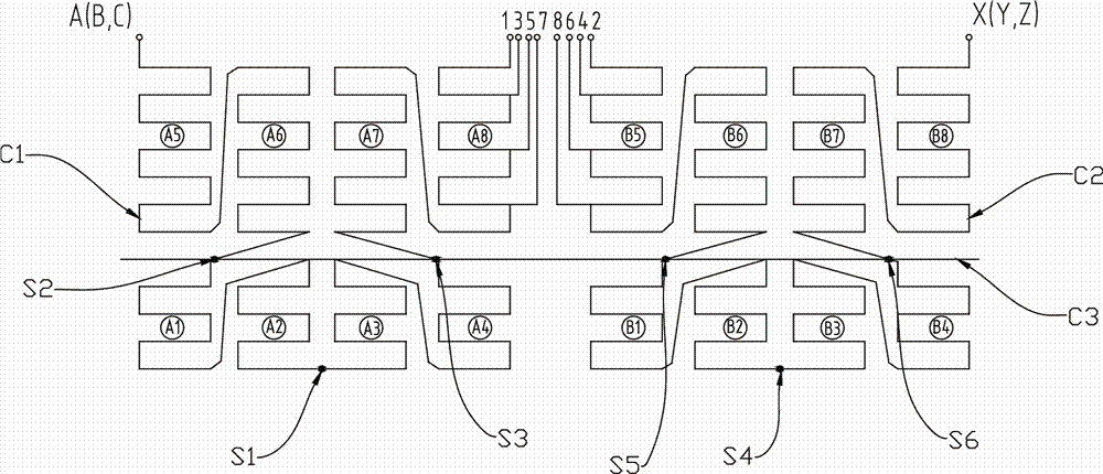
[0022] See Figure 1 to Figure 2 , a high-voltage coil winding method, including a symmetrical structure of the first winding coil C1 and the second winding coil C2, air channel plate C3; the first winding coil C1 includes the first welding point S1, the second Second welding spot S2, third welding spot S3, first coil A1, second coil A2, third coil A3, fourth coil A4, fifth coil A5, sixth coil A6, seventh coil A7, eighth coil A8 , the second winding coil C2 includes a fourth welding spot S4, a fifth welding spot S5, a sixth welding spot S6, a ninth coil B1, a tenth coil B2, an eleventh coil B3, a twelfth coil B4, The thirteenth coil B5, the fourteenth coil B6, the fifteenth coil B7, and the sixteenth coil B8; the steps are as follows:

[0023] Step a: Wind the wire from the first welding point S1 to the third coil A3, wind it to the airway pl...


PUM

PropertyMeasurementUnit
lengthaaaaaaaaaa

Abstract

The invention discloses a high-voltage coil winding method. A cross-type winding structure is used to wind the high-voltage coil, and the coil is divided into two ends by an air channel plate for winding. There are only two welding points on the bottom layer, which are wound to the coil side by side. After the airway plate in the center is wound to both sides with a cable-stayed wire structure, after the bottom layer winding is completed, the layer is raised, and the cable-stayed wire structure is continued to be wound; this winding method reduces solder joints and ensures product reliability .

Description

technical field [0001] The invention relates to the technical field of transformers, in particular to a winding method of a high-voltage coil. Background technique [0002] In recent years, my country's power demand has grown rapidly. According to the global power transformer research report, it is estimated that by 2019, the global power transformer market will increase to 28.69 billion US dollars, with a compound annual growth rate of 7.7% during the period; high-speed power grid construction and investment have driven The market demand for power transmission and transformation equipment; the huge investment in power construction has brought opportunities and challenges to the transformer industry, which has promoted the rapid development of the transformer industry. [0003] The transformer consists of an iron core (or magnetic core) and a coil. The coil has two or more windings. The winding connected to the power supply is called the primary coil, and the remaining windin...

Claims


Application Information

Patent Timeline
Patent Type & Authority Patents(China)
IPC IPC(8): H01F41/066
Inventor 刘天凤
Owner NINGBO AUX HIGH TECH
Learn More