Broadband combiner

A combiner and broadband technology, applied in the field of communication, can solve the problems of large return loss, insertion loss, failure to meet the use requirements, and low power capacity of the antenna feed network, and achieve improved assembly efficiency, compact structure, and combined circuits The effect of increasing the loss of the

Inactive Publication Date: 2016-11-23
TONGYU COMM INC
View PDF8 Cites 14 Cited by
  • Summary
  • Abstract
  • Description
  • Claims
  • Application Information

AI Technical Summary

Problems solved by technology

However, if this combiner device is not designed well, it will bring large return loss and insertion loss to the entire ant

Method used


Image

  • Broadband combiner
  • Broadband combiner
  • Broadband combiner

Examples


Embodiment Construction

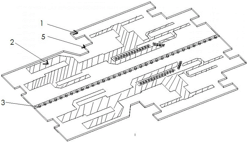
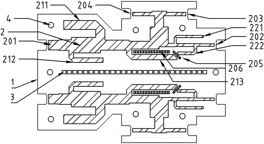
[0045] Such as figure 1 with figure 2 The invention provides a broadband microstrip combiner. The circuit board 1 adopts a dielectric board material with high dielectric constant and low loss. The circuit board adopts an integrated design and has two combiner units 2, the two combiner units are arranged side by side and mirrored, the output ports are placed on both sides of the circuit board, and the back of the combiner is a whole piece of copper Floor 5. Each combiner unit has two input ports 201 and 202, and the radio frequency signals of the two filters are combined to output 203 and 204 through two output ports. Each combiner unit has four welding points, and the welding points are welded to the coaxial cable, corresponding to two input ports and two output ports.

[0046] In the foregoing embodiment of the present invention, a short-circuit metallized via strip 3 is added between the two combiner units to reduce the electromagnetic coupling between the combiner units and...


PUM


Abstract

The invention provides a broadband combiner, which comprises a circuit board, wherein at least one combiner unit is arranged on the circuit board, is provided with an input end and an output end, and comprises a first filter and a second filter; an input port of the first filter is a first input port, and an input port of the second filter is a second input port; the first and second input ports are arranged back to back and axially distributed; signals of different frequency bands are input from the first and second input ports, and are filtered and synthesized for output through the output end of the combiner unit; the output end is arranged on one side of the first and second input ports. The broadband microstrip line combiner is small in size and high in out-of-band rejection performance, third-order intermodulation and power capacity, and has a broader working frequency band, as well as relatively lower return loss and insertion loss within the working frequency band, the design cost is reduced, and a larger space is provided for deployment of another feed network to facilitate assembling.

Description

【Technical Field】 [0001] The present invention relates to the field of communications, in particular to a broadband combiner. 【Background technique】 [0002] Mobile communication construction has entered the era of site sharing. Base station antennas directly determine the signal coverage and communication quality of the communication network. At present, the construction of mobile communication networks faces a shortage of site resources and space resources. With the integration of multiple networks, the same base station antenna is promoted to support multiple different frequency bands, such as the 1710-2690MHz ultra-wideband antenna, which saves construction funds and reduces the use of space resources. [0003] In actual network coverage, different standard frequency bands sometimes require different coverage effects. For example, 1880-2025MHz needs to be tilted down by 2 degrees, and 2575-2635MHz needs to be tilted down by 8 degrees, but 1710-2690MHz ultra-wideband base statio...

Claims


Application Information

Patent Timeline
IPC IPC(8): H01P1/213
CPCH01P1/213
Inventor 王灿梁建辉何振炬张理栋李泓霖
Owner TONGYU COMM INC
Why Eureka
Try Eureka