A waveguide coaxial conversion device output from the narrow side

A waveguide coaxial conversion, narrow edge technology, applied in the field of electronic communication, can solve problems such as cost increase, volume and weight increase, deterioration of system performance, etc., and achieve the effects of wide relative bandwidth, small insertion loss, and low standing wave.

Active Publication Date: 2018-09-04
PIVOTONE COMM TECH
View PDF5 Cites 0 Cited by
  • Summary
  • Abstract
  • Description
  • Claims
  • Application Information

AI Technical Summary

Problems solved by technology

In this case, the above two types of waveguide coaxial conversion cannot directly realize the output from the narrow side of the waveguide due to the inherent defects of its structure, and must cooperate with a series of turning structures of the waveguide or cable to achieve
As a result, it will inevitably increase the size and weight, which is not conducive to the miniaturization requirements of the overall system, and the cost will increase. At the same time, it will increase the complexity of the whole machine and deteriorate the system performance.

Method used


Image

  • A waveguide coaxial conversion device output from the narrow side
  • A waveguide coaxial conversion device output from the narrow side

Examples


Embodiment Construction

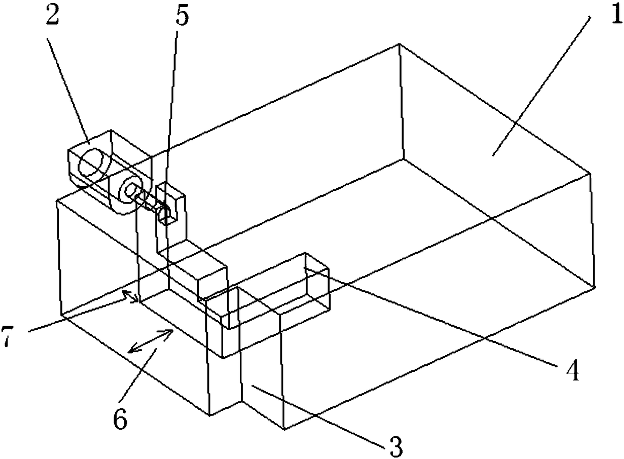
[0014] figure 1 is the internal three-dimensional diagram of the new waveguide coaxial conversion device, including the port of the rectangular waveguide 1; 2 is the 50 ohm coaxial port 2 (the port can also be a microstrip line port according to needs); the rectangular waveguide 1 is far away from the coaxial port A step 3 is cut on one side of the step 2, and controlling the length and width of the step 3 can improve the echo of the entire waveguide-to-coaxial conversion device. A boss 4 is set in the cavity of the rectangular waveguide. The boss 4 has multiple steps. The number of steps is determined by the bandwidth required to work. The wider the bandwidth required, the more the number of steps is required. In this embodiment, the boss 4 includes three steps, wherein the first step is the lowest, the last step is the highest, and the middle steps are increased in turn. There is a 90-degree turning structure in the middle of the boss 4, the first step is facing the directi...


PUM


Abstract

The invention discloses a waveguide coaxial converter providing output from a narrow side, comprising a rectangular waveguide and a coaxial port that is positioned on the narrow side of the rectangular waveguide; the other side of the rectangular waveguide opposite to the narrow side where the coaxial port is positioned is provided with a step at one corner; a chamber of the rectangular waveguide is internally provided with a boss having a plurality of steps, the steps increase in height sequentially, the lowest step right faces a waveguide port, other steps turn by 90 degrees and right face the narrow side of the rectangular waveguide output by the coaxial port, and the coaxial port is positioned at the highest step. The coaxial port of the waveguide coaxial converter is mounted on the narrow side of the rectangular waveguide, the rectangular waveguide is provided with a boss structure having a turn, close to an end surface, a core of a coaxial connector is welded directly to the upper portion of the boss, and conversion from the waveguide to coaxiality is achieved. The waveguide coaxial converter of such form has wide relative bandwidth, low standing wave and low insertion loss.

Description

technical field [0001] The invention belongs to the technical field of electronic communication, in particular to a waveguide coaxial conversion device output from a narrow side. Background technique [0002] The waveguide coaxial conversion device is an extremely important passive device in radar system equipment, guidance system equipment, microwave communication equipment and microwave test system. It is used to convert the electromagnetic wave signal in the waveguide into a coaxial or microstrip transmission line, which is convenient for the subsequent signal processing of the system. [0003] The design requirements of the waveguide coaxial conversion device: small insertion loss, low standing wave, large bandwidth and small size. At present, there are two most common rectangular waveguide coaxial conversion devices, one is the most common orthogonal mode waveguide coaxial conversion device, the coaxial output port of this form of waveguide coaxial conversion device is...

Claims


Application Information

Patent Timeline
Patent Type & Authority Patents(China)
IPC IPC(8): H01P5/08
CPCH01P5/08H01P5/085
Inventor 江顺喜周方平殷实梁国春梁文超赵媛媛林身平项显冯冬琼
Owner PIVOTONE COMM TECH
Why Eureka
Try Eureka