Antenna array system and control method

An antenna array direction and antenna array technology, applied in the field of mobile communication, can solve the problem of low efficiency of antenna sending and receiving signals, achieve the effect of improving sending and receiving efficiency and reducing SAR value

Inactive Publication Date: 2016-11-23
COOLPAD SOFTWARE TECH (SHENZHEN) CO LTD
View PDF2 Cites 19 Cited by
  • Summary
  • Abstract
  • Description
  • Claims
  • Application Information

AI Technical Summary

Problems solved by technology

[0005] The technical problem to be solved by the present invention is to provide an antenna array system, a control

Method used


Image

  • Antenna array system and control method
  • Antenna array system and control method
  • Antenna array system and control method

Examples


Embodiment 1

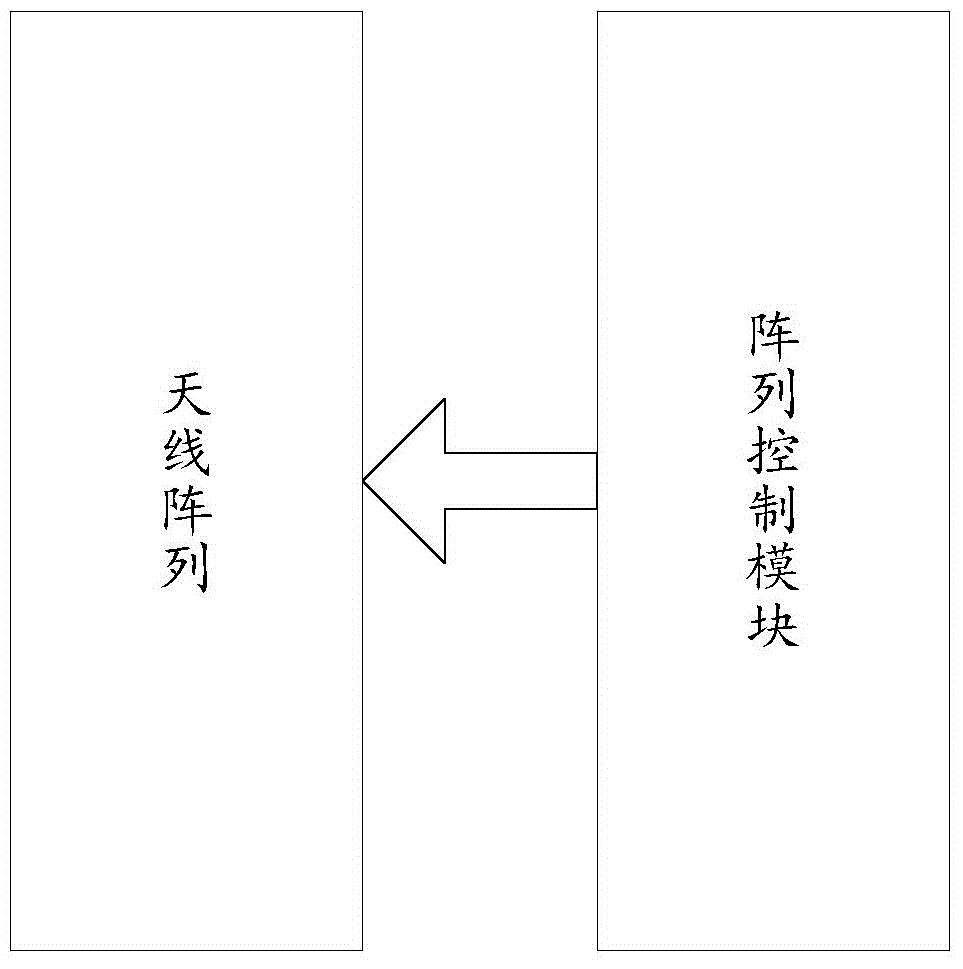
[0045] figure 1 is a schematic structural diagram of an antenna array system in an embodiment of the present invention, such as figure 1 As shown, the system includes:

[0046] The array control module is used to control the radiation direction of the antenna array pattern so that the main lobe of the antenna array pattern faces the direction of the maximum signal strength of the base station;

[0047] Wherein, the antenna array includes a plurality of antenna elements; the array control module is specifically used to control the radiation direction of the pattern of the antenna array by controlling the phase of each antenna element, so that the main lobe of the antenna array pattern is directed toward the base station The direction in which the signal strength is greatest.

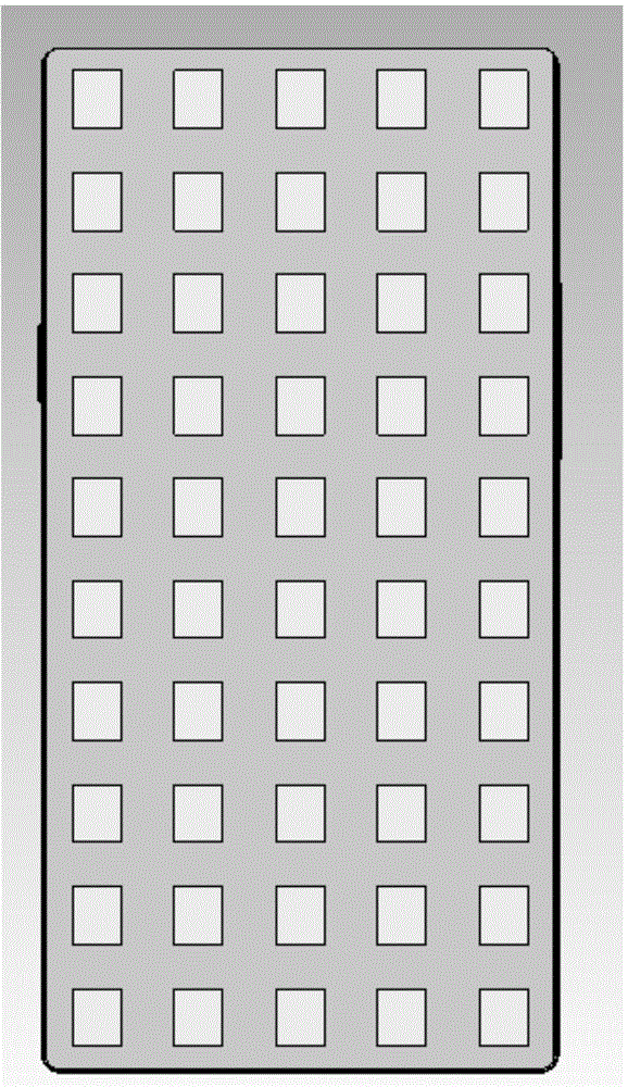
[0048] The array control module includes several array element control modules corresponding to multiple antenna elements;

[0049] Each array element control module is used to obtain direction informa...

Embodiment 2

[0061] Figure 8 It is a flowchart of a control method corresponding to the antenna array system described in Embodiment 1 of the present invention; Figure 8 As shown, the method includes:

[0062] S801. Control the radiation direction of the antenna array pattern, so that the main lobe of the antenna array pattern transmits and receives signals toward the direction with the highest signal strength of the base station;

[0063] Specifically, the antenna array includes a plurality of antenna elements;

[0064] By controlling the phase of each antenna element, the radiation direction of the pattern of the antenna array is controlled.

[0065] That is to say, after coupling part of the signals received by the antenna array elements, power detection is performed to obtain the direction information with the highest signal strength of the base station;

[0066] According to the direction information of the maximum signal strength of the base station, the phase of the correspondi...

Embodiment 3

[0072] The terminal in this embodiment of the present invention uses the antenna array system described in Embodiment 1 to transmit and receive signals.

[0073] It should be noted that since this embodiment includes all the content of Embodiment 1, the terminal described in this embodiment also has the technical effect described in Embodiment 1, and details are not described here.


PUM


Abstract

The invention discloses an antenna array system, a control method and a terminal. The antenna array system comprises an array control module and an antenna array, wherein the array control module is used for controlling the radiation direction of an antenna array pattern to enable a main lobe of the antenna array pattern to face the direction with the maximum base station signal strength; and antenna array is used for transmitting and receiving signals under control of the array control module. Through adjusting the antenna pattern, the main lobe of the antenna radiates towards the base station direction in a non-stop mode, the transmission efficiency of the mobile terminal is improved, and a SAR (Specific Absorption Rate) value is reduced.

Description

technical field [0001] The invention relates to the field of mobile communication, in particular to an antenna array system and a control method. Background technique [0002] Most of the existing mobile phone antennas use FPC (Flexible Printed Circuit Board, flexible printed circuit board) antennas, or PIFA (Planar Inverted F Antenna, Flat Inverted F Antenna) using LDS (Laser-Direct-structuring, laser direct forming technology), or Using IFA (inverted F antenna), the working principle is to use the mobile phone battery cover and the main board area as the main ground, and radiate electromagnetic waves outward. The latest three-section metal back cover antenna is equivalent to using a metal shell as an antenna, and its principle is basically the same as that of traditional FPC. The mobile phone antenna of the above structure has the following defects: [0003] Because the antenna radiation patterns of existing mobile phones are basically messy, the main lobe of the lower m...

Claims


Application Information

Patent Timeline
IPC IPC(8): H01Q21/00H01Q3/44
Inventor 刘豫青王吉钊陆洋李克
Owner COOLPAD SOFTWARE TECH (SHENZHEN) CO LTD
Why Eureka
Try Eureka