
Electric control cabinet with dehumidification function

A technology for power control cabinets and control cabinets, which is applied in the direction of electrical components, circuit devices, substations/power distribution device shells, etc., and can solve problems such as no alarms, damp power control cabinets, and normal power transmission of the power grid, so as to save electricity. Avoid interference, avoid damage effect

Inactive Publication Date: 2016-11-23
国网山东省电力公司鱼台县供电公司 +1
View PDF5 Cites 6 Cited by
  • Summary
  • Abstract
  • Description
  • Claims
  • Application Information

AI Technical Summary

Problems solved by technology

[0003] With the continuous development and progress of economic construction, more and more power control cabinets are built in the open air environment. The power control cabinets in the open air environment for a long time are easily affected by the outside world, resulting in moisture inside the power control cabinet. As a result, various power devices in the power control cabinet cannot work normally, affecting the normal power transmission of the entire power grid
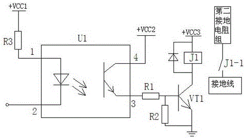
[0004] In addition, although the neutral point of the distribution cabinet in the prior art adopts the operation mode of grounding through resistance, it only plays the role of grounding and does not issue an alarm, so that the staff cannot obtain the alarm information in time; this is the prior art inadequacies of

Method used


Image

  • Electric control cabinet with dehumidification function
  • Electric control cabinet with dehumidification function
  • Electric control cabinet with dehumidification function

Examples


Embodiment Construction

[0048] The present invention will be described in detail below with reference to the accompanying drawings and specific embodiments. The following embodiments are explanations of the present invention, but the present invention is not limited to the following embodiments.

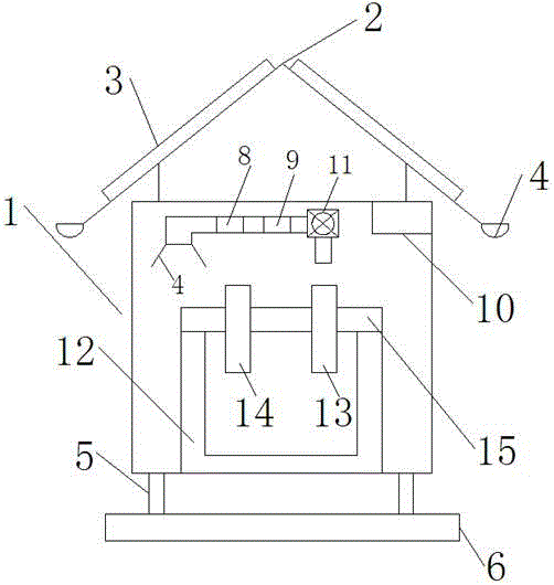
[0049] Such as Figures 1 to 4 As shown, a power control cabinet with a dehumidification function provided by the present invention includes a cabinet body 1; the top of the cabinet body 1 is provided with an inverted V-shaped top cover 2, and the two sides of the inverted V-shaped top cover 2 are provided with There is a heat insulation board 3, and the bottom edge of the inverted V-shaped top cover 2 is provided with a water guide groove 4;

[0050] The bottom of the control cabinet is provided with legs 5, and the legs 5 are fixed on the bottom plate 6 arranged on the ground;

[0051] A suction funnel 7 is arranged in the cabinet, and the suction funnel 7 is connected with a pipeline, and the pipeline i...


PUM


Abstract

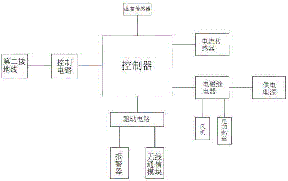
The invention relates to an electric control cabinet with a dehumidification function. The electric control cabinet comprises a cabinet body, and is characterized in that an inversed V-shaped top cover is arranged at the top of the cabinet body; thermal baffles are arranged on two side plates of the inversed V-shaped top cover; a water guiding groove is formed in the edge of the bottom end of the inversed V-shaped top cover; outriggers are arranged at the bottom of the control cabinet and fixed on a base plate of the floor; an air suction funnel is arranged in the cabinet body and connected with a pipeline; the pipeline is connected with a draught fan; a moisture absorption cavity and a drying cavity are arranged in the pipeline in sequence; a moisture absorption layer is arranged in the moisture absorption cavity; an electric heater strip is arranged in the drying cavity; the electric heater strip and the draught fan are connected to a power supply through an electromagnetic relay; the electromagnetic relay is connected with a controller; and the controller is connected with a humidity sensor which is arranged in the control cabinet.

Description

technical field [0001] The invention belongs to the technical field of power equipment, and relates to a power control cabinet, in particular to a power control cabinet with a dehumidification function. Background technique [0002] The power control cabinet is an important part of the power system and plays a very important role in the entire power grid transmission process. [0003] With the continuous development and progress of economic construction, more and more power control cabinets are built in the open air environment. The power control cabinets in the open air environment for a long time are easily affected by the outside world, resulting in moisture inside the power control cabinet. As a result, various power devices in the power control cabinet cannot work normally, affecting the normal power transmission of the entire power grid. [0004] In addition, although the neutral point of the distribution cabinet in the prior art adopts the operation mode of grounding...

Claims


Application Information

Patent Timeline
Patent Type & Authority Applications(China)
IPC IPC(8): H02B1/28H02B1/30H02B1/56H02B1/16H02J13/00G08B21/24
CPCG08B21/24H02B1/16H02B1/28H02B1/30H02B1/56H02J13/0006Y02B90/20Y04S40/126
Inventor 王爱民张海波杜中启段胜超徐欢
Owner 国网山东省电力公司鱼台县供电公司
Learn More