Constant temperature and humidity power distribution cabinet

A constant temperature and humidity, power distribution cabinet technology, used in electrical components, non-electric variable control, machines using electrical/magnetic effects, etc.

Active Publication Date: 2016-11-23
南京信德龙通信技术有限公司
View PDF8 Cites 10 Cited by
  • Summary
  • Abstract
  • Description
  • Claims
  • Application Information

AI Technical Summary

Problems solved by technology

However, when the external environment is high temperature and high humidity, it is not suitable to use heating for dehumidification, and there are obviously technical defects.

Method used


Image

  • Constant temperature and humidity power distribution cabinet
  • Constant temperature and humidity power distribution cabinet
  • Constant temperature and humidity power distribution cabinet

Examples


Embodiment 1

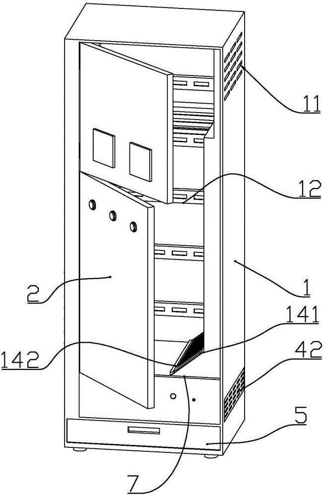
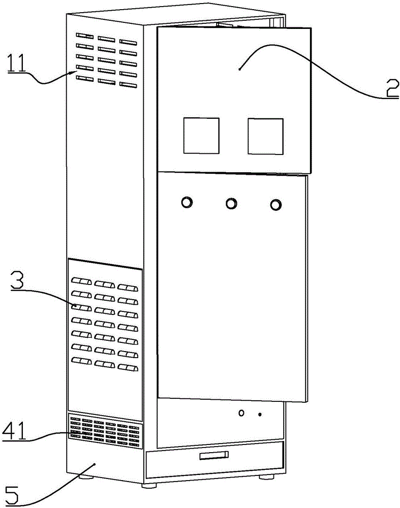
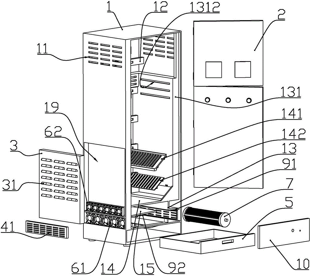
[0071] according to Figure 1 to Figure 17 As shown, this embodiment is a constant temperature and humidity power distribution cabinet, including a cabinet body 1 with a front opening, and a cabinet door 2 connected to the front end of the cabinet body through hinges; a mounting frame 12 is installed at the rear of the cabinet body ; The left and right sides of the upper part of the cabinet are formed with air outlets 11 .

[0072] The bottom of the cabinet body is formed with a slope plate 16 that is high on both sides and low in the middle; in the cabinet, the rear side of the cabinet is the rear cabinet, and the bottom of the rear cabinet is located above the middle of the slope. A stepper motor 8 is installed. The output shaft of the stepping motor is connected with a cooling plate assembly 7 arranged horizontally along the front and back direction of the cabinet.

[0073] The cooling chip assembly 7 includes two circular end blocks 74 of plastic material, more than one s...

Embodiment 2

[0089] according to Figure 1 to Figure 17 As shown, this embodiment is a constant temperature and humidity power distribution cabinet, including a cabinet body 1 with a front opening, and a cabinet door 2 connected to the front end of the cabinet body through hinges; a mounting frame 12 is installed at the rear of the cabinet body ; The left and right sides of the upper part of the cabinet are formed with air outlets 11 .

[0090] The bottom of the cabinet body is formed with a slope plate 16 that is high on both sides and low in the middle; in the cabinet, the rear side of the cabinet is the rear cabinet, and the bottom of the rear cabinet is located above the middle of the slope. A stepper motor 8 is installed. The output shaft of the stepping motor is connected with a cooling plate assembly 7 arranged horizontally along the front and back direction of the cabinet.

[0091] The cooling chip assembly 7 includes two circular end blocks 74 of plastic material, more than one s...


PUM


Abstract

The invention discloses a constant temperature and humidity power distribution cabinet. The power distribution cabinet comprises a cabinet body with an opening in the front end, and a cabinet door connected to the front end of the cabinet body through hinges, wherein a slope board with two high sides and a low middle is formed in the inner bottom of the cabinet body; a stepping motor is mounted in the cabinet body and positioned above the middle of the slope board at the lower part of a rear cabinet board on the rear side of the cabinet body; a refrigerating sheet component horizontally arranged in the lateral direction of the cabinet body is connected with an output shaft of the stepping motor; a front baffle is mounted at the lower part of the front side of the cabinet body; a first guide plate is fixedly connected with the interior of the cabinet and positioned on the upper left part of the refrigerating sheet component in the cabinet body; an upper air inlet is formed in the left side and positioned between the first guide plate and the second guide plate; an upper fan is mounted in the upper air inlet; an upper air inlet plate is connected with the outer wall of the left side of the cabinet body and positioned above the upper air inlet; air outlets are formed in the left and right sides of the upper part of the cabinet body. The power distribution cabinet is simple and compact in structure, and is applicable to the utilization in various complex condition environments.

Description

technical field [0001] The invention belongs to the field of electric equipment, and in particular relates to a structure of a constant temperature and humidity power distribution cabinet. Background technique [0002] The power distribution cabinet is to assemble switchgear, measuring instruments, etc. in a closed or semi-closed metal cabinet according to the requirements of electrical wiring. The Chinese patent with the document number CN104613672A discloses a semiconductor high-voltage cabinet dehumidification device. The shape of the invention is a sheet-like body made of semiconductor refrigeration sheets, and its heating surface is attached to the high-voltage power distribution cabinet through heat-conducting silicone grease. On the inner wall of the metal shell, its cooling surface is close to a layer of metal film. The outer surface of the metal film is a polished plane. There is an inclined bus bar on the plane. The bus bar leads to the high-voltage power distribut...

Claims


Application Information

Patent Timeline
Patent Type & Authority Applications(China)
IPC IPC(8): H02B1/56G05D27/02F25B21/02
CPCF25B21/02F25B2321/003G05D27/02H02B1/565
Inventor 周佳斌
Owner 南京信德龙通信技术有限公司
Why Eureka
Try Eureka